
Summary of A Digital temperature meter using an LM35 temperature sensor using PIC16F688
This article outlines a beginner-friendly digital thermometer project using a PIC16F688 microcontroller and an LM35 temperature sensor. The system converts analog voltage from the sensor into digital data via an internal ADC, displaying the temperature in both Celsius and Fahrenheit on a 16×2 LCD. The design employs a custom reference voltage circuit using diodes to enhance measurement accuracy for temperatures between 0°C and 100°C.
Parts used in the Digital Thermometer Project:
- PIC16F688 microcontroller
- LM35 temperature sensor
- 16×2 character LCD
- 5K potentiometer
- Zener diode or simple diodes (two diodes)
- Resistor (3.6K or 1K)
Introduction
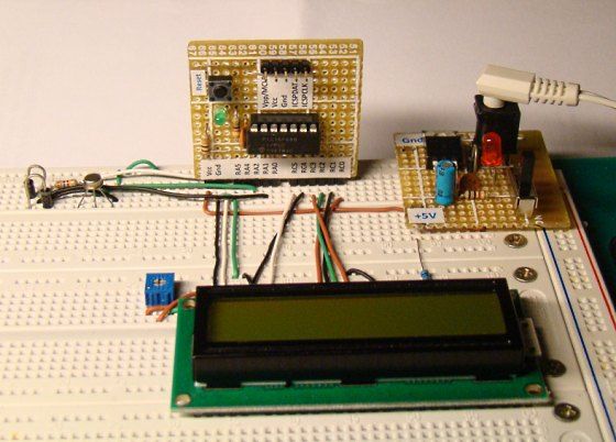
A digital thermometer is a good choice of project for beginners who just stepped in to the world of microcontrollers because it provides an opportunity to learn using sensors to measure the real world signals that are analog in nature. This article describes a similar project based on a PIC16F688 microcontroller and an LM35 temperature sensor. LM35 is an analog sensor that converts the surrounding temperature to a proportional analog voltage. The output from the sensor is connected to one of the ADC channel inputs of the PIC16F688 microcontroller to derive the equivalent temperature value in digital format. The computed temperature is displayed in a 16×2 character LCD, in both °C and °F scales.
Theory
The LM35 series of temperature sensors are produced by National Semiconductor Corporation and are rated to operate over a -55 °C to 150°C temperature range. These sensors do not require any external calibration and the output voltage is proportional to the temperature. The scale factor for temperature to voltage conversion is 10 mV per °C. The LM35 series sensors come in different packages. The one I used is in a hermatic TO-46 transistor package where the metal case is connected to the negative pin (Gnd).
The measurement of negative temperatures (below 0°C) requires a negative voltage source. However, this project does not use any negative voltage source, and therefore will demonstrate the use of sensor for measuring temperatures above 0°C (up to 100°C).
The output voltage from the sensor is converted to a 10-bit digital number using the internal ADC of the PIC16F688. Since the voltage to be measured by the ADC ranges from 0 to 1.0V (that corresponds to maximum temperature range, 100 °C), the ADC requires a lower reference voltage (instead of the supply voltage Vdd = 5V) for A/D conversion in order to get better accuracy. The lower reference voltage can be provided using a Zener diode, a resistor network, or sometime just simple diodes. You can derive an approximate 1.2V reference voltage by connecting two diodes and a resistor in series across the supply voltage, as shown below. As a demonstration, I am going to use this circuit in this project. I measured the output voltage across the two diodes as 1.196 V. The resistor R I used is of 3.6K, but you can use 1K too. The important thing is to measure the voltage across the two diodes as accurate as possible.
We need do some math for A/D conversion. Our Vref is 1.196 V, and the ADC is 10-bit. So, any input voltage from 0-1.196 will be mapped to a digital number between 0-1023. The resolution of ADC is 1.196/1024 = 0.001168 V/Count. Therefore, the digital output corresponding to any input voltage Vin = Vin/0.001168. Now, lets see how to get the temperature back from this whole process of converting sensor’s output to 10-bit digital number.
Assume, the surrounding temperature is 26.4 °C. The sensor output will be 264 mV (0.264 V). The output of ADC will be 0.264/0.001168 = 226. If we reverse this process, we have 226 from ADC and we can go back and find the temperature by using the sensor scale factor (10 mV/°C),
temperature = 226 * 0.001168 (V/Count) / 0.01 (V/°C) = 26.4 °C
If you want to avoid floating point math in your program, just use,
temperature = 226 * 1168 = 263968
While displaying this, you need to put a decimal at the fourth place from the left. So the calculated temperature is 26.3968°C, which is pretty close to the actual one. The difference is caused by quantization and rounding errors. In this project, we will display temperature accurate to one decimal place, i.e., we will divide the above number by 1000 to get 263. So the temperature will be displayed as 26.3 °C.
Once you have derived the temperature back in °C, you can convert it to °F using a simple equation,
temperature in °F = 9 x temperature in °C /5 + 32
In this case, the number you got for °C is scaled by 10 (263 for 26.3), you should use
temperature in °F = 9 x temperature in °C /5 + 320
Since, the number for °C may not be exactly divisible by 5 (such as 263 is not), you can further eliminate the floating point by scaling it one more time by 10. So the new equation will be,
temperature in °F = 9 x temperature in °C x 10 /5 + 3200
or, temperature in °F = 18 x temperature in °C + 3200 = 18 x 263+3200 = 7934
79.34 °F is equivalent to 26.3 °C. In this project, it will be displayed as 79.3 °F.
Circuit Diagram
An external reference voltage to the internal ADC of PIC16F688 can be provided through RA1 I/O pin. The output from the LM35 sensor is read through RA2/AN2 ADC channel. The temperature is displayed on a 16×2 character LCD that is operating in the 4-bit mode. A 5K potentiometer is used to adjust the contrast level on the display. The detail circuit diagram is given below. Note that the PIC16F688 uses its internal clock at 4.0 MHz.
For more detail: A Digital temperature meter using an LM35 temperature sensor using PIC16F688
-
Why is this project suitable for beginners?
This project helps beginners learn how to use sensors to measure real-world analog signals using microcontrollers. -
How does the LM35 sensor work?
The LM35 converts surrounding temperature into a proportional analog voltage with a scale factor of 10 mV per °C. -
What is the purpose of the diode circuit in this project?
The diode circuit provides a lower reference voltage of approximately 1.2V to the ADC for better accuracy instead of using the full 5V supply. -
What temperature range can this specific project measure?
Since no negative voltage source is used, the project measures temperatures above 0°C up to 100°C. -
How is the analog signal converted to a digital value?
The internal ADC of the PIC16F688 converts the sensor output voltage into a 10-bit digital number ranging from 0 to 1023. -
Which pins are used for the reference voltage and sensor input?
The external reference voltage is provided through the RA1 I/O pin, while the sensor output is read through the RA2/AN2 ADC channel. -
How is the temperature displayed in Fahrenheit calculated without floating point math?
The formula uses integer scaling: temperature in °F equals 18 times the scaled Celsius value plus 3200. -
What clock speed does the PIC16F688 use in this circuit?
The PIC16F688 operates using its internal clock at 4.0 MHz.
