Summary of Hand Sign Lock
Summary: The Hand Sign Lock uses an OV7670 CMOS camera and a PIC32 microcontroller to authenticate users by recognizing three gestures: fist, open hand, and no hand. It applies an adaptive Otsu thresholding method to convert camera luminance frames into binary images, calibrates per-user lighting and gesture sizes, and offers calibration, matching, and password-reset modes with a TFT interface and two buttons. The system is portable, processes images on the PIC32, and demonstrates reliable matching under controlled lighting, though sensitivity to illumination and camera limitations remain challenges.
Parts used in the Hand Sign Lock:
- OV7670 CMOS camera module
- PIC32 microcontroller
- TFT display (thin film transistor screen)
- Two push buttons (mode and confirm/move)
- PULL-UP resistor for button wiring
- Clock output from PIC32 (10 MHz XCLK to camera)
- Wiring/connectors between camera, PIC32, and TFT
- Power supply components (implied for PIC32, camera, TFT)
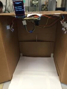
- Enclosure or box and internal light source (used experimentally)
Introduction
Security using technology is a growing and expanding field to protect against the user’s identity or property. As more advanced tools are developed, security has begun to expand to utilize a person’s physiology as a key instead of a password; for example, newer models of IPhones by Apple have fingerprint sensors as an option instead of a passcode. However, one drawback is that a person’s physiology cannot be changed, and in the example with the fingerprint sensors, once multiple users is able to obtain reproduce the fingerprints to gain access, it is difficult to determine the correct user. To deal with this disadvantage, some security systems may utilize a password as well as biological information for identification.
For this final project, the goal is to utilize a series of hand signs as a method of authentication. Because the size and shape of the hand are different for each person, hand signs will also depend on the user’s physiology. The combination and the pattern of hand signs serves as the password component of the authentication process. Using a CMOS image sensor, the PIC32 microcontroller will analyze pictures to match the appropriate hand sign to each picture and determine whether the sequence of hand signs or gestures are correct. At the current state, the hand signs are only limited to a fist and an open hand to provide for binary values as a key. However, the project is functional and can reliably determine whether the input sequence is correct and if the system allows access to the user.
Overview
Our project will improve the usability of a generic lock and key system. While gestures are easy to mimic, this project provides an entertaining approach for a simple security system. However, our device will check only for a fist, an open hand, and no hand. To clarify, as depicted in Figure 2-1, a fist is when all fingers are curled, and an open hand is when all fingers are extended. While this system will not be used to protect anything soon, the device focuses on improving home automation and improving the quality of life by implementing a security system that utilizes simple gestures or hand signs as the pass code.
The idea of this project was inspired by a combination of past projects, primarily the “CMOS Camera Rock Paper Scissors Game System” by Ling-Wei Lee and Kevin Tang from the Spring 2010 semester. Ling-Wei and Kevin Tang utilized white gloves with black tape to determine the hand sign or gesture, and we wanted to improve upon this project without gloves and tapes and just the user’s hand. The project is also inspired by the “SingLock” by Sang Min Han and Alvin Wijaya from the Fall 2014 semester. They utilized the user’s voice signature as part of the authentication process. From these two projects, we developed the Hand Sign Lock, which is a combination of the two projects with our own improvements and design.
Background Math
Before discussing the design of the Hand Sign Lock, we need to mention the algorithm utilized for image processing. For this project, the Hand Sign Lock stores an image from the CMOS camera and must determine the hand sign or gesture that it corresponds to. Thresholding is used on the image to clearly distinguish the user’s hand from the white background, more specifically Otsu’s method for clustering-based image thresholding.
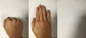
Overall, Otsu’s thresholding method splits the histogram into two classes, which correspond to the foreground and the background of the image. The algorithm iterates through every possible threshold value to determine the variance for both classes. Using the following equation,

the weighted sum of the variance can be calculated at each iteration. The threshold is determined to be the value of the iteration at which the weighted sum of the variances are at the minimum. However, for this project, the thresholding is slightly modified from the original algorithm. The smallest two weighted sum are selected, and the average of the two thresholds is the final threshold. This modification allows for images to take into account two possible locations to separate the foreground and the background.
Logical Structure
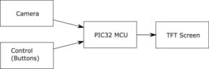
As depicted in Figure 2-3, the Hand Sign Lock demonstrates the high-level design of the project and can be divided into four main parts: CMOS camera, control, PIC32 microcontroller, and thin film transistor (TFT) screen. The OV7670 CMOS camera provides images for the PIC32 microcontroller, and the buttons in the control module allows the user to select the appropriate mode and to perform actions when calibrating or resetting the password. The PIC32 microcontroller utilizes Otsu’s method for thresholding to transform the grayscale image to a binary (black and white) image. In addition, the microcontroller has multiple modes for a more intuitive user interface and constantly updates the TFT screen with the appropriate messages. Depending on the mode, after a image is received from the CMOS camera, the image is printed to the TFT screen for the user to view as well as for debugging purposes, which is helpful for determining functionality of the calibration step and evaluating the results from the thresholding algorithm.
Hardware and Software Tradeoffs
All of the classification of the hand signs and gestures are performed on the PIC32 microcontroller, which is implemented in C. However, some of the example past ECE4760 projects handle the processing by sending the image to MATLAB for a more powerful processor. If MATLAB was incorporated into the design, a wider variety of tools would be available, which would improve the results, but we want the processing to be done on the PIC32 microcontroller for portability because the microcontroller better resembles the processing unit utilized by home automation and security systems. In addition, there is a tradeoff between the speed of the image capture and quality of the image. At the default settings, the CMOS camera outputs the image data too fast for the microcontroller to handle, and the resulting image would appear distorted. As a result, the frame rate from the camera had to be decreased, but having a slower image rate impacts the overall useability of the security system because of the time that the user must wait while recording a picture. Any movement will also distort the resulting image because the image rate also relates the exposure time of the camera. With a slow frame rate, the quality of the image is high, but all objects in the camera must not be moving.
Standards
For the OV7670 CMOS camera, a variety of standards are available for us to select. First, I2C communication is utilized for writing the registers of the camera and allows for programming the settings. Next, we selected the QCIF scaling, which is the smallest standard scaling that the camera offers. QCIF corresponds to a picture of (176 by 144 pixels), which is enough in terms of this project. Finally, another standard used is YUV422 color format for displaying the color, and for the specifications of this project, only the luminance (Y) is used because only the grayscale image is necessary for thresholding and generating a binary (black-white) image.
Related Copyrights and Existing Patents
Based on our research, there are not any commercial products related to this project, but a past ECE4760 project resembles the Hand Sign Lock. The existing project is Gesture Based Security Lock by Ankur Thakkar, Darshan Shah, and Saisrinivasan Mohankumar from Fall 2013, which uses infrared proximity sensors to determine distance from sensor and direction. While the projects are similar in concept, our implementation and design are different because of the use of a CMOS camera. In addition, the user’s hand is stationary for each picture of the Hand Sign Lock.
Design
Hardware Design
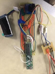
The hardware of the Hand Sign Lock consists mainly of a CMOS camera, a PIC32 microcontroller, a TFT screen, and two buttons. The schematic for connecting all the modules together are depicted in the Appendix B below.
Camera Module :
The main part of this project is to collect image data and transfer the image to the microcontroller reliably. For the CMOS camera, we chose Omnivision’s OV7670 CMOS CameraChip with OmniPixel Technology. Some of the past ECE4760 projects utilize the C3088 camera, but in terms of cost, the OV7670 camera is a better option while satisfying our specifications. We configured the PIC32 microcontroller to output a 10[MHz] clock for the OV7670 camera module, which is in the acceptable input clock range. Also, CMOS image sensor has a clock prescaler that controls the frequency of the pixel clock (PCLK). This prescaler is important and necessary for proper functionality as the PIC32 is not fast enough to handle a high clock speed. In addition, the default setting for the output drive capability (COM2) is set to 2x, which increases the frame rate speed by 2. For this project, we set the prescaler to be 16, and the PCLK can be determined using
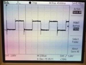
As depicted in Figure 3-2, the resulting waveform has a period of approximately 8.5[μs], which is approximately 118[kHz]. This frequency for the PCLK is slow, and each picture using the QCIF standard requires about 0.21[s], or roughly 5[fps]. The OV7670 module has a vast amount of registers to control a variety of setting and video configuration options, which are detailed in the datasheet. While we left most of the values in the default state, we did change some of the register values to allow for smooth data transfer from the camera to the PIC32. However, the OV7670 module utilizes SCCB communication protocol, which is similar to the I2C protocol. Two pins on the PIC32 and two on the camera module are used for programming: signal clock and a bidirectional data wire. The PIC32 must write data to the camera, so with the I2C peripheral library, we can send data across the data channel with a signal clock speed of one-eigth of the peripheral bus clock. Before the data is sent, the camera must receive the “write slave address” or the serial EEPROM address, which has a hex value of 0x42. Next, we need to send the register address that we want to change the value of. Finally, we can send the data.
| Register | Address | Default Value | Value Used | Description |
|---|---|---|---|---|
| COM3 | 0x0C | 0x00 | 0x08 | Bit[3]: enable scaling for using QCIF format |
| COM7 | 0x12 | 0x00 | 0x08 | Bit[3]: use QCIF format |
| CLKRC | 0x11 | 0x80 | 0x90 | Bit[6]: enable scaling for using QCIF format Bits[0-5]: Clock Prescaler (for this project, set to 0b10000 |
All other register are set to the original default values. The wiring and connections between the OV7670 module with the microcontroller are depicted in Figure B-1 of Appendix B. In addition, some other hardware utilized are the buttons for improving user interface. In Figure B-1, the buttons are connected in series to a pull-up resistor. The project utilizes a pull-up resistor, so the pin is set to be active low. Finally, Figure B-2 depicts the connections between the PIC32 microcontroller with the TFT screen.
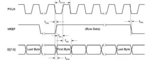
It can be seen from the image frame timing shown below provided by the OV7670 data sheet that every pulse of the VSYNC signal indicate a new frame and every rising edge of HREF represents a start of a new column and every falling edge represent the end of that row. For the pixel clock, every rising edge indicates a valid data coming out of the parallel output pins (D[7:0]), and the data coming out of that pins at other times are all invalid and we should only read one word from the D[7:0] with one pixel clock cycle.
User interface :
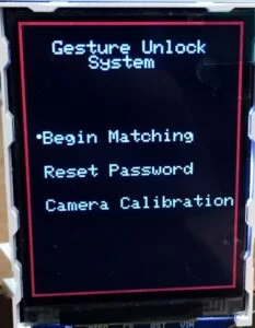
The TFT display used here is mainly used for the user interface. When first open the microcontroller, there will be a welcome page consist of three different options including: ‘Begin Matching’ mode, ‘Reset Password’ mode, and ‘Calibration’ mode. The mode is controlled by two buttons one for choosing and one for confirm.
Software Design
Image Storate & pre-process :
While the actual ram of the MCU is 0x8000 which is 32kb, the smallest image the camera can get is QCIF format (consist of 176 x 144 pixels), and two bytes for each pixel, which is about 50Kb total and exceeds the total amount of storage. In order to minimize the image data, we change the image format to YUV and only take the value of Y (luminance component and the amount of white light of a color) to compute. By doing this we could get a minimized image of 25kb.
But instead of storing the whole pixel values we come up with another idea of transfer the image to a binary image using appropriate threshold. So we first compute the histogram for the current frame, and use the histogram for this frame to compute the threshold using otsu’s threshold method and use that threshold to translate the next frame to a binary image. We could only get this done by reading the VSYNC, HREF and PCLK all the time and decide the time to read the image data by their performance. Thus we had to make the pixel clock slow enough as we said before.
Three Modes:
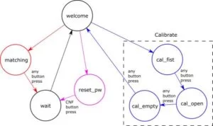
There are three different mode in this system including calibration mode, matching mode, and reset password mode. These different modes are controlled by a state machine depicted in the figure above. And the calibration should be done before two other modes when the system is first turned on.
Calibration Mode:
In the calibration mode, the user will be asked to do the fist and open hand gestures as well as an empty space. The images will be analyzed due to choose the threshold for the current lightning condition, and calculate the parameter of two different gestures for the current size of the hand. And the image of empty space will be used to minimize the effect of the shadows.
Since the camera module is quite sensitive to light, the threshold should be adaptive due to the current lighting condition. But during the matching mode the image should also have the same threshold as it does in the calibration mode, or it will be hard to find a match with the gesture stored. As a result, we will choose the threshold value due to the first two images taken in the calibration mode and get it fixed until the shutdown of the system or the start of another calibration. After the threshold is chosen, the system will take three pictures for each gesture and choose the median value of the black pixels as the parameter to match.
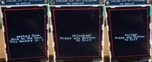
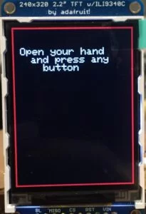
Begin Matching Mode:
In this mode, the camera will take five pictures based on the pre-determined threshold and calculate the number of black pixels for each picture as the input password sequence. Between each picture there will be a sign on the screen to inform the user to move on to the next one. Then the input password will be matched with the password stored and see if that matched or not. A ‘1’ represents a fist, a ‘2’ represents an open hand, and a ‘0’ represents an empty.
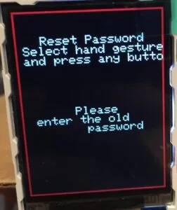
Reset Password Mode:
In this mode, the user will be asked to input the old password as it did in the begin matching mode. If the password did not match, user will not be allowed to reset the password. If the password matches with the old one, the user could choose a gesture and press the ‘move’ button to store it. This step could be done at most five times. The user could also end this mode early by press the ‘confirm’ button, then the rest of the unchanged passwords will be remained and form a new password together with the password entered. For example, if the old password is ‘fist, fist, hand, hand, hand’ and the new password before ‘confirm’ is ‘hand, fist, fist’, then the later two ‘hand’ will be preserved and the new password will be ‘hand, fist, fist, hand, hand’.
Results
Accuracy:
The adaptive threshold method worked quite well, when the lighting condition is good and there is little shadow around the hand, and it will always find a good value to show up the whole hand with only a little of black dots on the corner. And since the threshold value is done only once in the calibration mode, the matching part more accurate. Also, the value of black pixels for each gesture is not fixed but set in the calibration mode, it works quite well for different people with different size of hand. As long as the user follow the steps, performs the calibration, put their hand in the pre-defined region, the matching part work very accurate.
To test for accuracy, we utilized unit testing to ensure the Hand Sign Lock could recognize our hand. First, we calibrate the Hand Sign Lock with the user’s hand. Next, we modified the matching mode to continuously check for the hand gesture instead of the current setup for the demo, which is five frames before failing the authentication process. With the continuous setup, the matching mode enables us to debug and test efficiently.
Stability:
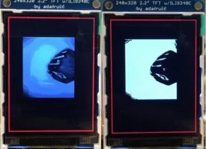
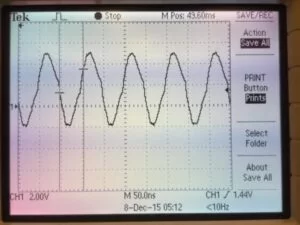
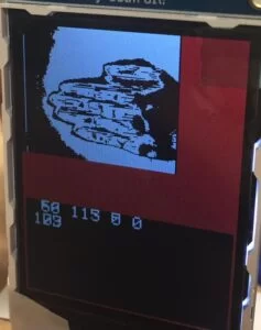
The OV7670 camera module is actually very hard to control and is very sensitive to lighting condition, even a slight change of lighting condition will result in a huge difference of the output image as depicted in the figure above. The black pixels at the left side of the TFT screen is a result of the gradient caused by the light source and the box. Therefore, lighting is an important factor and can create problems with the Hand Sign Lock’s gesture recognition. Thus, if the lightning condition is changed between the calibration and matching mode, the effect of adaptive threshold will not be as reliable. And the possible range of different gestures will have relatively big overlap, which makes it hard to identify one from another. In fact, we had to change to a different thresholding agorithm to the Otsu’s method in order to obtain better binary images. Another problem is that, when the light is too strong, the pixel value of the hand and the background are very close and threshold will no longer worked because there will be only a small amount of pixels left, making almost no difference of the pixel numbers of difference gestures. When the light is too weak, there will be a lot of shadow on the processed image, overlapping part of the hand. In order to fix that problem, we tried to put the whole product in a box and put some light source inside to control the lightning condition, but finding it hard to choose a proper light source.
Conclusions
Expectations and Future Work
Overall, this project was a success. The Hand Sign Lock was able to determine the gesture pattern between a fist, open hand, and no hand. Each of the three modes (calibration, matching, and reset password) worked reliably and improved the usability of the security system. However, based on our original project proposals, we wanted to also differentiate between the number of fingers that the user is signaling the system. With this feature, the Hand Sign Lock will be more complicated and harder to hack. The user will have many more options in terms of the combination of hand signs that can be used for the password. While not great, the binary key setup with a fist and open hand demonstrates the functionality, and we can improve on our design. One problem that we were unable to complete the goals stated in our project proposal was the difficulty we faced when dealing with the OV7670. The CMOS camera module costed us countless number of hours and significantly impeded our progress.
However, this project can have many different improvements that would increase functionality. First, our current implementation only observes the amount of pixels below the threshold to determine the hand sign. The system also ignores all chrominance data and only store the luminance values for a grayscale picture. One improvement would be to utilize the chrominance data in conjunction with the thresholding technique to allow for a better estimate of the hand using skin color. Another improvement would be to increase the complexity of the algorithm for determing the hand sign or gesture. Because machine learning is usually associated with object recognition in images, we could implement a MATLAB script for post processing and analysis to provide coefficients for the PIC32 microcontroller to make a decision.
Standards
Our project followed the I2C protocol for writing the register values of the OV7670 camera module to modify the settings for proper functionality with the microcontroller. In addition, we followed the QCIF scaling, which is the smallest scaling for us to use. For our project, having more pixels for each picture would not improve our design. Finally, we also utilized the YUV422 standard for the luminance values, but we did not take advantage of the chrominance values in our hand sign determination algorithm.
Intellectual Property Considerations
Even though our project is inspired by several projects such as “CMOS Camera Rock, Paper, Scissors Game System” and the “Sing Lock”, our project is unique, and none of the code from other projects were copied. In addition, we had some references that provided invaluable data for understanding the OV7670 and how to reliably record images. Only the details of the words were used to inspire us to come up with our own solution and implementation. Finally, we also implemented the Otsu’s method for thresholding after fully understanding the algorithm and rewrote it to use in our project. However, all of the work that is reference by this project are properties of their respective authors and are not for personal gain.
Ethical Considerations
The IEEE Code of Ethics were constantly considered throught the design and implementation of this project. For our current design, we were careful that the Hand Sign Lock would take into considereation the safety, health, and welfare of the public. For the final prototype of the project, the Hand Sign Lock did not have any exposed wires that could harm the user. From all of our testing, the results stated above are honest and represent actual data recorded for this project. All of our claims and estimates are based on the available data gathered when developing or debugging. In addition, we hope that this project improves the understanding for future groups to utilize CMOS camera. While the CMOS camera was difficult to setup, the task is not impossible, and this project can mitigate potential uncertainties with using CMOS image sensors. We have not accepted any types of bribes and will continue to uphold this standard. While we had the technical understanding to undertake this project, we had not done a project similar to the Hand Sign Lock, so this project will maintain and improve our technical competence. We sought and accept criticism of our work from the TA’s as well as from Professor Bruce Land to constantly improve our project design. We also did not injure others, their property, reputation, or employment by false or malicious actions.
Legal Considerations
Our project is not related to any legal restrictions that we know of besides copyright and intellectual property, which are discussed in “Intellectual Property Considerations”.
Source: Hand Sign Lock
- What gestures does the Hand Sign Lock recognize?
The system recognizes a fist, an open hand, and no hand. - How does the Hand Sign Lock separate hand from background?
It uses an adaptive thresholding method based on Otsu's algorithm applied to the luminance (Y) channel to convert images to binary. - Can the system change thresholds for different lighting conditions?
Yes, calibration mode selects an adaptive threshold based on initial calibration images and fixes it until shutdown or a new calibration. - Does the image processing run on the PIC32 or externally?
All classification and image processing are performed on the PIC32 microcontroller in C. - What image format and resolution are used?
The camera uses QCIF scaling (176 x 144) and YUV422 format, but only the Y (luminance) component is used. - How many frames are captured during matching mode?
The system takes five pictures during matching mode to form the input password sequence. - How are gestures encoded for the password?
A fist is encoded as 1, an open hand as 2, and an empty as 0 to build a sequence. - What user interface elements are available?
A TFT display presents modes and prompts; two buttons allow mode selection and confirmation/move actions. - Can the password be reset on the device?
Yes, in Reset Password mode the user must input the old password and then enter up to five new gestures before confirming. - What are main limitations noted in the article?
The OV7670 camera is sensitive to lighting; changes between calibration and matching lighting reduce reliability, and the system currently uses only binary gestures.