
Summary of PIC 12F675 Programmable 12V Battery Monitor
This article describes a programmable 12V battery monitor using a PIC12F675 MCU, a 78L05 regulator, and a resistor divider to measure battery voltage via the internal ADC. It provides an adjustable, non-irritating buzzer alarm (three short beeps every 15 seconds) when voltage falls below a user-set threshold via a 3-pin header and jumper. The design supports various 12V battery types, measures up to ~15V with ~15mV resolution, and can be built on veroboard or a PC board; the PIC must be programmed with the provided HEX before final assembly.
Parts used in the Battery Monitor:
- R1 10K resistor
- R2 100K 1% resistor
- R3 47K 1% resistor
- C1 0.1uF capacitor
- C2 0.1uF capacitor
- IC1 Microchip PIC12F675
- IC2 78L05 voltage regulator
- SG1 5V piezo buzzer
- JP1 3-pin header with mini jumper
- Veroboard or printed circuit board
- Optional IC socket
- Heat shrink for enclosure
Being an active outdoor guy, I have a few different types of 12V lights and a variety of battery types.
– For flying RC planes and quadcopters at night, we use sealed lead acid batteries to power our club tables.
– For fishing, I have a few 12V 2W led lights, powered by 2200mA, 3 cell LiPo batteries.
– For camping, the tent and trailer lights are using 12V sealed lead acid batteries, and portable lights 2200mA 3 cell LiPo batteries.
As I do not want to totally discharge any of my batteries, I decided to design this battery monitor.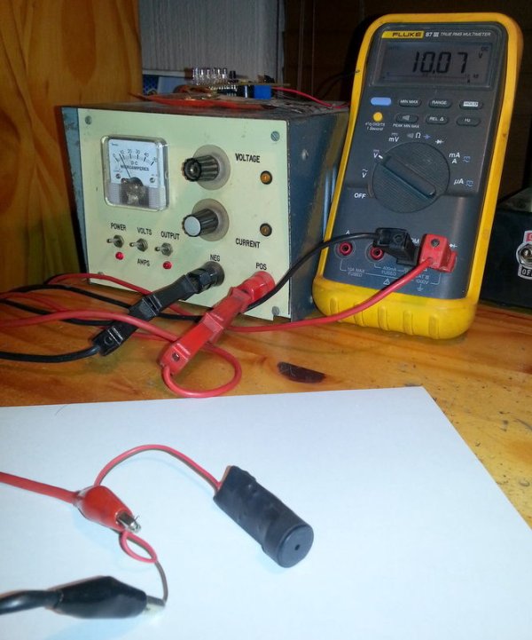
Features needed:
– Easy to use and install permanently.
– To be able to use on any battery type used for 12V lights.
– Non-irritating alarm.
– Adjustable alarm pick-up value.
Instead of setting the alarm value using a pot, I opted for an easy programmable option, thus the need for a microcontroller (PIC 12F675).
The 12F675 is powered via the 78L05 regulator, and this voltage is also the A/D converter reference voltage. Using a resistor voltage divider (R2 & R3), the battery voltage is measured using the internal A/D converter of the 12F675.. This divider values were chosen such that the maximum measurable voltage of the 12F675 will be around 15V, with a resolution of around 15mV.
The buzzer is a standard 5V piezo buzzer, and will give 3 short beeps ever 15 seconds once the battery voltage is below the alarm value.
Programming of the alarm level is obtained with a 3-pin header and mini jumper.
Specifications:
Maximum input voltage 20V
Minimum input voltage 8V
Minimum alarm voltage level 8V
Maximum alarm voltage level 15V
Idle current 3.12mA
Alarm voltage resolution 15mV
Step 1: Building the Battery Monitor
You will need the following components:
R1 10K resistor
R2 100K, 1% resistor
R3 47K, 1% resistor
C1, C2 0.1uf capacitors
IC1 Microchip PIC 12F675
IC2 78L05 voltage regulator
SG1 5V piezo buzzer
JP1 3 pin header, with mini jumper
Build the circuit using veroboard or PC Board.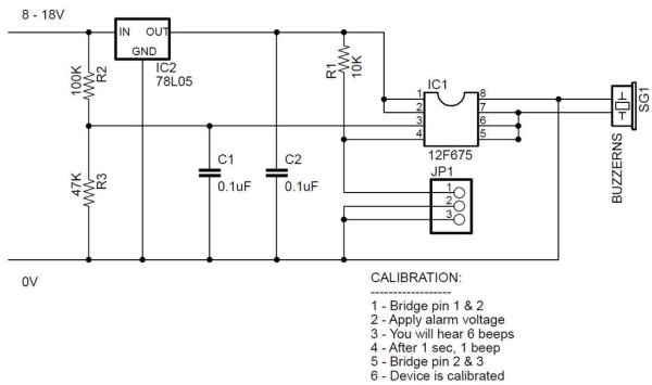
Step 2: Using PC Board
As I wanted to build a couple of this Battery Monitors, I opted to make a couple of PC boards. Using the free version of Eagle, I was able to make 12 boards at once on the 100 x 80 PC Board.
However, the circuit is easy enough to build on a piece of strip board.
Step 3: Assembly
Using the PC Boards, assembly took only a few minutes per board. After testing the circuit, I used heat shrink to cover the project to keep costs down.
PLEASE NOTE:
The PIC 12F675 needs to be programmed first. Please upload this HEX file first before soldering on the 12F675, or use an IC socket.
For more detail: PIC 12F675 Programmable 12V Battery Monitor
- What battery types can this monitor be used with?
It can be used on any battery type used for 12V lights as stated in the article. - How is the alarm level adjusted?
The alarm level is programmed using a 3-pin header and a mini jumper rather than a potentiometer. - What microcontroller is used in the design?
The project uses a Microchip PIC12F675. - How does the monitor measure battery voltage?
Battery voltage is measured by the PIC12F675 internal A/D converter via a resistor voltage divider (R2 and R3) with the 78L05 regulator providing the A/D reference. - What is the alarm behavior when voltage is below the threshold?
The buzzer emits three short beeps every 15 seconds when the battery voltage is below the alarm value. - What is the measurable voltage range and resolution?
The maximum measurable voltage is around 15V with an alarm voltage resolution of about 15mV. - What are the specified maximum and minimum input voltages?
The specifications list a maximum input voltage of 20V and a minimum input voltage of 8V. - What is the idle current of the monitor?
The idle current is specified as 3.12mA. - Do I need to program the PIC before assembly?
Yes, the PIC12F675 must be programmed with the provided HEX file before soldering it in place, or you should use an IC socket.
