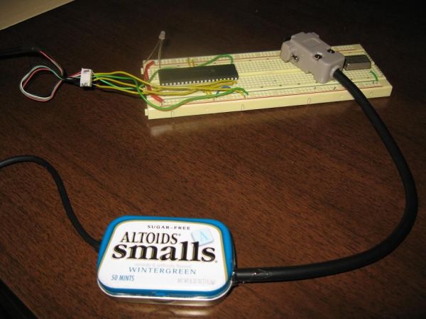
Minty JDM PIC Programmer
This project details how to build a JDM style programmer to program PIC Microcontrollers using Microchip’s ICSP (In Circuit Serial Programming) and freeware software (PICPgm). Total project cost: less than $10. This device has been tested on both the PIC16F877 and PIC18F4550. Check the PICPgm website to see compatibility with other PIC microcontrollers.
I used information from http://www.olimex.com/dev/images/PIC/PIC-USB-4550-sch.gif and Ian’s excellent instructible http://www.instructables.com/id/Business-Card-PIC-Programmer/ to complete this project.
Step 1
Parts and Tools
Most of these parts are fairly common and can be found at Digikey, All Electonics, or Radio Shack:
(1) DB9 Female Serial port connector w/ at least a 5 wire cable attached (Connector was $4.50)
(1) Cable with 5 wires and a connector to connect to PIC circuit (I used an old mouse cable)
(1) 1.5K Ohm Resistor ($0.14 ea)
(1) 10K Ohm Resistor ($0.14 ea)
(4) 1N4148 Diodes ($0.18 ea)
(1) 8.2V Zener Diode ($0.32 ea)
(1) 5.1V Zener Diode ($0.27ea)
(2) BC547 Transistors ($0.41 ea)
(1) 22uF Tantalum Capacitor ($0.32 ea)
(1) 100uF Electrolytic Capacitor ($0.27 ea)
(1) Small Prototype Board ($1.99 ea)
(1) Small Mint Tin (Had one laying around)
Some small guage wire for connections
Tools required:
– Soldering Iron and Solder
– Wire Strippers
– Multimeter (for checking connections)
Step 2
Layout
I chose to layout my components in a straight line and make the connections on the back side of the board. Take a look at the schematic on the next step if you wish to have a different layout. If you use this layout, MAKE SURE YOU GET THE DIODES, CAPS, AND TRANSISTORS PLACED PROPERLY! Notice that the last diode is placed opposite of the others. Make sure you have the capacitors oriented to connect the negative lead to ICSP pin #3.
Step 3
Schematic
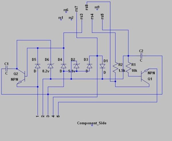
Here is the schematic for circuit. The circuit uses power from the serial port to power the PIC microcontroller during programming. Some USB to Serial converters do not work with this circuit because of the voltage needed on the PIC’s mclr pin. This circuit works best with on board ports or serial cards. For the ICSP pins, they are connected to the microcontroller as follows:
1. MCLR Pin
2. VDD Pin(s)
3. VSS Pin(s)
4. PGC Clock Pin
5. PGD Data Pin
Step 4
Soldering
Once the components are in place, solder the pins together as directed by the schematic in the previous step. Use wire to jumper points together as needed. I tested all connections a couple times with the multimeter to make sure that everything was connected properly and that points weren’t shorted together. I’ve attached a schematic to this step that is a mirrored version of the original, it comes in handy when soldering and testing the connections. It shows the view of the circuit as seen from the solder side.
For more detail: Minty JDM PIC Programmer using PIC18F4550 microcontroller


