Summary of Exploring the World of PIC Microcontrollers: An Architectural Overview
The article overviews PIC microcontrollers (RISC, Harvard architecture), their memory, I/O ports, timers, ADC, oscillators, CCP module and special peripherals, compares popular PIC variants, and presents a vehicle-detecting street-light project using IR sensors and a PIC to light LEDs ahead of a vehicle and turn off lights behind to save energy.
Parts used in the Street Light that Glows on Detecting Vehicle Movement:
- PIC microcontroller (e.g., PIC16 series such as 16F84/16F628/16F877/18F452)
- IR sensors (positioned on either side of the road)
- LEDs (street light LED blocks)
- Power supply components: step-down transformer
- Rectifier (diodes)
- Filter capacitor(s)
- Voltage regulator
- Crystal or RC components for oscillator (crystal and capacitors or resistor and capacitor)
- Resistors (for LEDs and sensors)
- Capacitors (for filtering, oscillator modes, decoupling)
- Optional UART/A/D interfacing components (if using ADC or serial features)
A Peripheral Interface Microcontroller (PIC), developed by General Instruments Microcontrollers in 1993, operates under software control and is programmed to execute various tasks, regulating production lines. PIC microcontrollers find application in diverse fields including smartphones, audio accessories, and cutting-edge medical devices.
Various PIC microcontrollers are available in the market, spanning from the PIC16F84 to the PIC16C84, offering affordable flash capabilities. Microchip has recently expanded its lineup to include flash chips like the 16F628, 16F877, and 18F452. While the 16F877 comes at twice the cost of the older 16F84, it boasts significantly larger code capacity, increased RAM, an abundance of I/O pins, as well as additional features such as UART, A/D converter, among others.
PIC Microcontrollers Architecture
The PIC microcontroller operates on RISC architecture, featuring a memory structure adhering to the Harvard design, where distinct memories are allocated for program and data, each with their own dedicated buses.
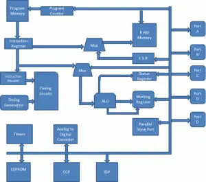
1. Memory Structure
The PIC architecture comprises two types of memory: Program memory and Data memory.
Program Memory: This memory space is structured as 4K*14 and is designated for storing either 13-bit instructions or program code. Access to the program memory data is facilitated through the program counter register, which retains the address of the program memory. The memory space at address 0000H serves as the reset memory space, while 0004H is allocated for interrupt handling.
Data Memory: The data memory is comprised of 368 bytes of RAM and 256 bytes of EEPROM. The RAM portion comprises multiple banks, each containing general-purpose registers and special function registers.
The special function registers encompass control registers responsible for managing various functionalities of the chip’s resources such as Timers, Analog to Digital Converters, Serial ports, I/O ports, and more. For instance, the TRISA register enables manipulation of its bits to modify the input or output functions of port A.
Meanwhile, the general-purpose registers are designated for storing temporary data and processing outcomes. These registers are all 8-bit in size.
Working Register: It comprises a memory space where operands for each instruction are stored, along with the results of each execution.
Status Register: The status register bits indicate the state of the ALU (Arithmetic Logic Unit) following each instruction execution. Additionally, they serve to choose one of the four RAM banks.
File Selection Register: It functions as a reference to any other general-purpose register, containing a register file address, and is employed in indirect addressing.
The program counter register, a 13-bit register, serves as another general-purpose register. Its 5 upper bits function as PCLATH (Program Counter Latch), operating independently like any other register, while the lower 8 bits act as the program counter bits. This program counter functions as a pointer directing to the instructions stored in the program memory.
EEPROM: The EEPROM of the microcontroller comprises 256 bytes of memory space. Functioning similarly to ROM in terms of permanence, it allows for erasure and alteration of its contents during microcontroller operation. Accessing and modifying the EEPROM’s contents is facilitated through special function registers such as EECON1 and EECON.
2. I/O Ports
The PIC16 series comprises five ports, namely Port A, Port B, Port C, Port D, and Port E.
Port A: This port is 16 bits wide and can function either as an input or output port, depending on the configuration set in the TRISA register.
Port B: This port operates at 8 bits and functions as both an input and output port. When configured for input, four of its bits are capable of being altered by interrupt signals.
Port C: It functions as an 8-bit port where its operation, whether input or output, depends on the status of the TRISC register.
Port D: This port operates as an 8-bit interface, serving not only as an input/output port but also functioning as a subordinate port linked to the microprocessor bus.
Port E: This 3-bit port also fulfills the role of providing control signals to the A/D converter in addition to its primary function.
3. Timers
PIC microcontrollers include three timers: Timer 0 and Timer 2 are 8-bit timers, while Timer 1 is a 16-bit timer that can also function as a counter.
4. A/D Converter
The PIC Microcontroller features an 8-channel, 10-bit Analog to Digital Converter (ADC). The functionality of the ADC is managed through specific special function registers, namely ADCON0 and ADCON1. ADRESL holds the lower 8 bits of the conversion result, while ADRESH stores the upper bits. A 5V analog reference voltage is necessary for proper operation.
5. Oscillators
Timing generation in PIC microcontrollers relies on oscillators. These oscillators, such as crystals or RC circuits, serve as external sources. When utilizing crystal oscillators, a crystal is linked between two designated pins, with the capacitor value on each pin dictating the oscillator’s mode of operation. These modes include low-power, crystal, and high-speed modes. Conversely, RC oscillators’ clock frequency is determined by the resistor and capacitor values, spanning from 30 kHz to 4 MHz.
6. CCP module:
A CCP module operates within three distinct modes:
Capture Mode: This mode records the arrival time of a signal, essentially capturing the Timer1 value when the CCP pin transitions to a high state.
Compare Mode: It serves as an analog comparator, producing an output once the timer1 value meets a specific reference threshold.
PWM Mode: It offers pulse-width modulated output featuring a 10-bit resolution and customizable duty cycle programming.
Additional special peripherals comprise a Watchdog timer, which initiates a reset of the microcontroller upon software malfunction, and a Brownout reset, which triggers a reset in response to power fluctuations, among others. To enhance comprehension of this PIC microcontroller, we provide a practical project that leverages this controller for its functionality.
Street Light that Glows on Detecting Vehicle Movement
The objective of this project is to create a system for controlling LED street lights, which is capable of detecting vehicle movement on the highway. It switches on a set of street lights in advance of the vehicle’s path, while simultaneously turning off lights behind it to conserve energy. The programming of a PIC microcontroller for this project is implemented using either embedded C or assembly language.
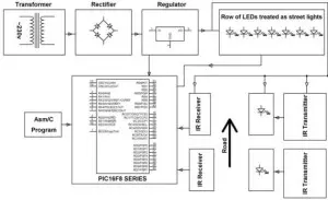
The power supply circuit functions to provide power to the entire circuit through a series of steps including stepping down, rectifying, filtering, and regulating the AC mains supply. During periods of no vehicle activity on the highway, all lights remain off to conserve power. Positioned on either side of the road, IR sensors detect vehicle movement and relay commands to the microcontroller, which controls the activation and deactivation of LEDs. When a vehicle approaches, a block of LEDs illuminates, adjusting its intensity or switching off as the vehicle passes by.
Projects utilizing PIC microcontrollers find application across various domains such as peripherals for video games, audio accessories, and more. Should assistance be required for any projects, feel free to reach out by commenting in the designated section.
- What is the objective of the street light project?
The objective is to control LED street lights so they turn on ahead of a vehicle and turn off behind it to conserve energy. - Which microcontroller family is used for the project?
The project uses PIC microcontrollers from the PIC16/PIC18 family. - How does the system detect vehicle movement?
IR sensors positioned on either side of the road detect vehicle movement and send signals to the microcontroller. - How are the LEDs controlled when a vehicle approaches?
The microcontroller receives sensor input and switches on a block of LEDs ahead of the vehicle and switches off lights behind it. - What powers the street light circuit?
A power supply consisting of stepping down, rectifying, filtering, and regulating the AC mains provides power to the circuit. - Can the PIC be programmed in different languages for this project?
Yes, the PIC can be programmed using embedded C or assembly language. - What role does the oscillator play in the PIC for this project?
The oscillator provides timing generation for the PIC using a crystal or RC circuit to generate the clock. - Does the project use ADC features of the PIC?
The article notes PICs have an 8-channel 10-bit ADC and ADC is managed via ADCON0 and ADCON1, implying ADC can be used if needed. - What peripherals help protect the PIC in operation?
Peripherals such as the Watchdog timer and Brownout reset help reset the microcontroller on software malfunction or power fluctuations.