dsPIC33 Recorder using dsPIC33FJ12GP201 with Proteus Simulation

Summary of dsPIC33 Recorder using dsPIC33FJ12GP201 with Proteus Simulation


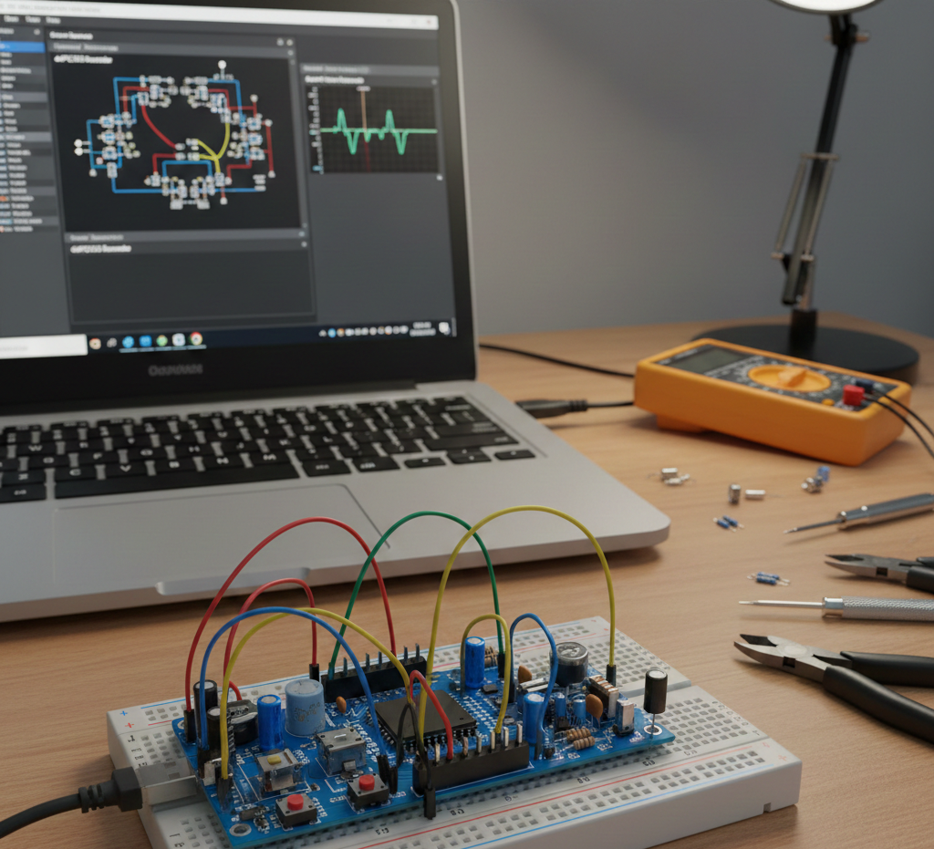
The dsPIC33 Recorder is a low-power data-logging project using a dsPIC33FJ12GP201 to periodically read temperature, humidity, and analog pressure, store records in I²C ferroelectric EEPROM, and return to ultra-low-power sleep. It uses timer and external interrupts, ADC averaging for pressure, UART command interface, and is fully simulated in Proteus VSM for educational and portable environmental monitoring applications.

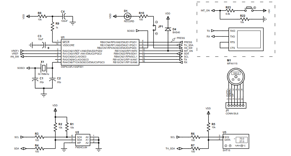
Parts used in the dsPIC33 Recorder:

  • dsPIC33FJ12GP201 microcontroller
  • Digital temperature and humidity sensor (SHT series)
  • Analog pressure sensor
  • I²C Ferroelectric EEPROM
  • 32.768 kHz crystal oscillator
  • UART serial interface (for terminal)
  • Resistors
  • Capacitors
  • Power conditioning components
  • Proteus VSM simulation environment (for testing)

Introduction

The dsPIC33 Recorder is a low-power microcontroller project designed to periodically record environmental data using a dsPIC33 digital signal controller. Built and tested in Proteus simulation, this project demonstrates how embedded systems can efficiently collect, process, and store sensor data over long periods.
It combines digital and analog sensing, non-volatile memory storage, and serial communication in a compact design.
This makes it an excellent practical electronics example for learning data logging, power management, and firmware structure on dsPIC devices.
The project is ideal for students and engineers exploring embedded systems, sensor interfacing, and low-power firmware design.

Embedded electronics prototyping setup
Illustrative View of the Concept.

How the Project Works (Overview)

The system periodically wakes up from low-power sleep, measures environmental parameters, stores them in non-volatile memory, and then returns to sleep.
A timer interrupt controls the sampling interval, while an external interrupt allows a serial terminal to interrupt normal operation.
The dsPIC33 reads temperature and humidity from a digital sensor, pressure from an analog sensor, and logs the values into I²C ferroelectric memory.
All timing, memory management, and sensor handling are managed in firmware.

Block Diagram / Workflow Explanation

  1. Timer1 Wake-Up

    • Low-power oscillator drives Timer1

    • dsPIC33 wakes up at a programmed interval

  2. Sensor Acquisition

    • Digital temperature & humidity read via sensor interface

    • Analog pressure read using ADC with averaging

  3. Data Processing

    • Raw sensor values combined into structured data

  4. Non-Volatile Storage

    • Measurements written sequentially into I²C memory

    • Memory header updated with new address

  5. Sleep Mode

    • MCU returns to ultra-low-power sleep until next cycle

  6. User Interrupt (INT0)

    • Serial terminal can interrupt recording for commands

Key Features

  • Periodic environmental data logging

  • Ultra-low-power sleep operation

  • Digital temperature and humidity measurement

  • Analog pressure measurement with averaging

  • I²C non-volatile memory storage

  • Interrupt-driven command interface via serial port

  • Fully simulated in Proteus VSM

Components Used

  • dsPIC33FJ12GP201 – Main controller

  • Digital Temperature & Humidity Sensor (SHT series)

  • Analog Pressure Sensor

  • I²C Ferroelectric EEPROM

  • 32.768 kHz Crystal Oscillator

  • UART Serial Interface

  • Resistors, capacitors, and power conditioning components

Applications

  • Environmental data logging

  • Portable weather monitoring devices

  • Battery-powered sensor nodes

  • Industrial condition monitoring

  • Embedded systems training and education

  • Low-power data acquisition systems

Explanation of Code (High-Level)

The firmware is structured into clear functional modules:

  • Initialization
    Sets oscillator, pin remapping, ADC, Timer1, UART, and interrupts.

  • Interrupt Handling

    • INT0 interrupt pauses logging and processes serial commands.

    • Timer1 interrupt handles periodic data acquisition and logging.

  • Sensor Functions
    Dedicated functions read pressure, temperature, and humidity.

  • Memory Management
    EEPROM header tracks memory usage and configuration parameters.

  • Power Management
    MCU enters sleep mode between measurements to minimize power draw.

Source Code

Download
#include "p33FJ12GP201.h"
#include "timer.h"
#include "utilities.h"
#include "analog.h"
#include "i2c_eeprom.h"
#include "SHTxx_drivers.h"
#include "serial.h"
#include "command_proc.h"
#include "common.h"

Proteus Simulation

In Proteus VSM, the recorder shows periodic wake-ups driven by Timer1.
Sensor values update during each active cycle, EEPROM addresses increment correctly, and UART communication responds immediately to external interrupts.
Power-down behavior is clearly visible as the MCU returns to sleep between samples.

(FAQs)

1: Why does the Proteus simulation pause periodically?

Because the dsPIC enters sleep mode between timer interrupts.

2: Can I change the sampling interval?

Yes, modify the time-base value stored in the EEPROM header.

3: Why is I²C turned off during sensor reading?

To avoid bus conflicts since sensors and EEPROM share clock lines.

4: Can this run on other dsPIC33 devices?

Yes, with minor pin-mapping and configuration changes.

5: Why is data averaged for pressure readings?

Averaging improves ADC stability and noise reduction.

6: Can I log more sensors?

Yes, if memory space and I/O pins are available.

7: Why use ferroelectric EEPROM?

It offers fast writes and very low power consumption.

Conclusion

This dsPIC33 Recorder project is a strong example of low-power embedded systems design using Proteus simulation.
It demonstrates real-world techniques such as sensor interfacing, EEPROM data logging, interrupt handling, and power optimization.
Perfect for learning and experimentation, this project provides solid hands-on experience with microcontroller projects and professional firmware structure.

Quick Solutions to Questions related to the dsPIC33 Recorder:

  • Why does the Proteus simulation pause periodically?
    Because the dsPIC enters sleep mode between timer interrupts.
  • Can I change the sampling interval?
    Yes, modify the time-base value stored in the EEPROM header.
  • Why is I²C turned off during sensor reading?
    To avoid bus conflicts since sensors and EEPROM share clock lines.
  • Can this run on other dsPIC33 devices?
    Yes, with minor pin-mapping and configuration changes.
  • Why is data averaged for pressure readings?
    Averaging improves ADC stability and noise reduction.
  • Can I log more sensors?
    Yes, if memory space and I/O pins are available.
  • Why use ferroelectric EEPROM?
    It offers fast writes and very low power consumption.
  • How does the system wake up to take measurements?
    Timer1 driven by a low-power oscillator wakes the dsPIC at the programmed interval.
  • How can a user interrupt recording?
    An external INT0 interrupt from a serial terminal can pause logging and process commands.

About The Author

Ibrar Ayyub

I am an experienced technical writer holding a Master's degree in computer science from BZU Multan, Pakistan University. With a background spanning various industries, particularly in home automation and engineering, I have honed my skills in crafting clear and concise content. Proficient in leveraging infographics and diagrams, I strive to simplify complex concepts for readers. My strength lies in thorough research and presenting information in a structured and logical format.

Follow Us:
LinkedinTwitter