Summary of Serial Data Received from PC and Displayed on 16×2 Using USART of Pic16f877 Microcontroller
Summary: This tutorial explains receiving serial data from a PC hyperterminal via RS-232, converting it with a MAX232, and displaying it on a 16x2 LCD using a PIC16F877 microcontroller. It covers required hardware, signal level conversion, PIC USART RX wiring, LCD connections, and outlines C code structure using Hi-Tech C and MPLAB to initialize ports, LCD, and USART for continuous reception and display.
Parts used in the Serial Data to 16x2 LCD with PIC16F877 Project:
- PIC16F877 Microcontroller
- 16x2 LCD
- MAX232 level shifter IC
- PC with DB-9 or DB-25 serial port (Hyperterminal)
- Potentiometer (for setting LCD contrast)
- 20 MHz crystal
- Connecting wires
- Power supply
Here is a simple tutorial on how to receive serial data from PC(Personal Computer) Hyperterminal and display it on 16×2 lcd using PIC16f877 microcontroller. Its not much difficult you just need to know how to use USART(Universal Syncronous-Asyncronous receiver transmitter) of PIC 16f877. Serial data is transmitted and recived by PC using DB-9 OR DB-25 port of PC.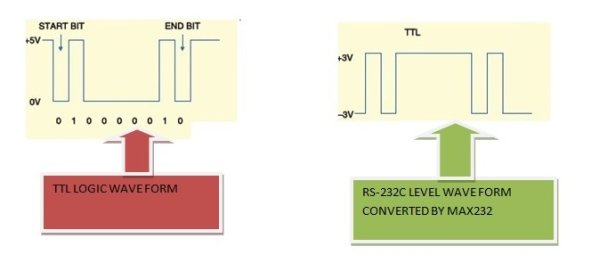
Project Requirements
- PIC16f877 Microcontroller
- 16×2 lcd
- MAX232
- PC with DB-9 or DB-25 Port
- Potentiometer (For Setting LCD Contrast)
- Crystal 20MHz
- Connecting Wires & Power Supply
Microcontrollers works on TTL(Transistor Transistor Logic) wave form & Standard PC(Personal Computers) works on RS-232 level wave form. Serial Data Transmitted by PC is in RS-232c level wave form. We have to convert this RS-232c wave form data in TTL form, to pass it to PIC16f877. The best way is to use MAX-232 ic. MAX-232 converts RS-232c level wave form data in TTL & TTL data in RS-232c level. Below is a simple Diagram of both the wave forms.
Port-B of PIC 16f877 is connected to data pins of 16×2 lcd. RS(Register-Select) Pin of lcd is connected to Port-D Pin#6. En(Enable) Pin of lcd is connected to Port-D Pin#7. RW(Read-Write) Pin is grounded Because we only want to write to lcd. You can also connect RW pin to Port-D Pin#5 Because Rw is also programmed in software burned in PIC 16f877.
USART of PIC 16f877 is present at Pin 25 & 26 of PIC 16f877 Microcontroller. USART Include Port-C Pin#6 & 7. RC6 can be used as TX(Transmission) and RC7 can be used as RX(Reception). Since we are receiving data from PC and then displaying it on 16×2 lcd so we are only concerned with RX(Reception) pin of USART. This RX pin is connected to Pin#12(R1OUT) of MAX-232. Pin#13(R1IN) of MAX-232 is connected to PIN#3 of DB-9 Port.
Some Tutorials Regarding the project are.
Both the tutorials above are very important for you, if you are new and didn’t use the stuff before in any project. I recommend you to go through them it will help you a lot in understanding the circuit diagram and working of both the things. Circuit diagram of the project is given below.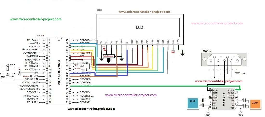
Code is written in c language using MPLAB-ide and High Tech C compiler is used to compile the code. First High Tech C-compiler header file htc.h is imported in the project. Then Crystal frequency is defined which is 20MHz. RD7,RD6 & RD5 pins of Port-D are initialized as EN, RS & RW, Control pins for 16×2 lcd. lcdcmd() function is sending commands to lcd and control these commands. display() function is sending data to lcd, controls this data by controlling EN,RW & RS pins of lcd. lcdint() function is initializing our lcd and Microcontroller ports.
In the main function first TRISC7=1 is initializing RX pin as input. TXSTA(Transmit Status and Control Register) is initializing USART in Asyncronous Mode with High Speed Baud Rate. 0x04 is loaded in TXSTA.
- What is the purpose of MAX232 in this project?
MAX232 converts RS-232 level signals from the PC to TTL levels for the PIC and converts TTL back to RS-232 as needed. - Which PIC pins are used for USART RX and TX?
USART uses RC6 (TX) and RC7 (RX); this project uses RC7 for reception. - How is the LCD connected to the PIC?
Port B is connected to the LCD data pins; RD6 is RS, RD7 is EN, and RW is grounded (or can be on RD5 if controlled by software). - What compiler and IDE are used for the code?
Code is written in C using MPLAB IDE and compiled with Hi-Tech C compiler. - How is the USART enabled in code?
USART is enabled by setting SPEN (bit 7) in RCSTA; the example loads 0x90 into RCSTA. - What frequency crystal is used for the PIC?
A 20 MHz crystal is used and defined in the code. - Which register configures asynchronous high-speed baud mode?
TXSTA is configured for asynchronous high-speed mode; the example loads 0x04 into TXSTA. - Where is the RX pin of PIC connected on the MAX232?
RC7 (RX) is connected to R1OUT (pin 12) of the MAX232, and R1IN (pin 13) of MAX232 connects to the DB-9 pin 3.