Summary of DC Motor Speed Control using Microcontroller PIC-16F877A
Summary: This project designs a closed-loop DC motor speed control system using a PIC16F877A microcontroller. An optical encoder provides speed feedback; the microcontroller implements a proportional (P) controller with Kp=1 and generates PWM to a motor driver to maintain desired speed under load variations. A Visual Basic 6 GUI lets users set target speed and view speed-versus-time graphs. Results show the built encoder is reliable and the PIC16F877A can regulate motor speed effectively.
Parts used in the DC motor speed control using Microcontroller PIC16F877A:
- PIC16F877A microcontroller
- DC motor
- Optical encoder (built during the project)
- Motor driver
- Power supply
- Microcontroller programmer (implied for PIC programming)
- Computer/laptop for GUI
- Visual Basic 6 software (for GUI)
- Connecting cables and PCB or prototyping hardware
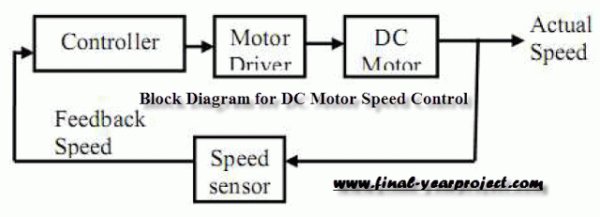
Micro-controller is a very widely used electronic component and today we are showing your another example of it. Today’s’ project topic is “DC motor speed control using Microcontroller PIC16F877A” and we are sharing full project report of it. This is a very good project work for final year Electronics and Electrical students. This project is mainly focus on DC motor speed control system by using microcontroller PIC 16F877A. It is a closed-loop real time control system, where optical encoder (built during this project) is coupled to the motor shaft to produce the feedback speed signal to controller.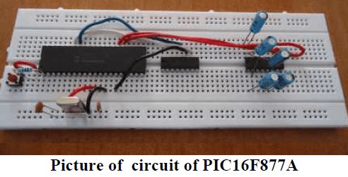
Pulse Width Modulation (PWM) technique is employed where its signal is generated in microcontroller. Micro-controller acts as proportional (P) controller with Kp =1 in this study. You can also Subscribe to FINAL YEAR PROJECT’S by Email for more such projects and seminar.
The PWM signal are going to be send to motor driver to vary the voltage provide to motor to take care of at constant speed. A program in Visual Basic 6 is developed to produce a graphic computer program (GUI) for the user to enter desired speed at laptop. Besides, it additionally shows a graph of motor speed versus time to let the user monitor the performance of the system simply. supported the result, the reading of optical encoder engineered is sort of reliable. Through the project, it may be ended that microcontroller PIC 16F877A will management motor speed at desired speed though there’s a variation of load.
 The goal of this project is to design a DC motor speed control system by using microcontroller PIC16F877A. It is a closed-loop real time control system. The controller will maintain the speed at desired speed when there is a variation of load. By varying the PWM signal from microcontroller (P controller) to the motor driver, motor speed can be controlled back to desired value easily.
For more detail: DC Motor Speed Control using Microcontroller PIC-16F877A
- What is the main controller used in the project?
The PIC16F877A microcontroller is used as the main controller. - How is motor speed feedback obtained?
Speed feedback is obtained from an optical encoder built and coupled to the motor shaft. - What control strategy is implemented in the microcontroller?
The microcontroller implements a proportional P controller with Kp = 1. - How is the motor speed adjusted?
Motor speed is adjusted by varying the PWM signal generated by the microcontroller and sent to the motor driver. - Can the system maintain desired speed under load variation?
Yes, the controller maintains the speed at the desired value when there is a variation of load. - Is there a user interface for setting speed?
Yes, a Visual Basic 6 GUI on a computer/laptop allows the user to enter desired speed and view speed versus time graphs. - Does the project include a built encoder or an off-the-shelf encoder?
The project uses an optical encoder built during the project. - What technique is used to control the average voltage applied to the motor?
Pulse Width Modulation PWM technique is used to vary the effective voltage applied to the motor.