Software UART (SoftUART) using TMS320F28027 Piccolo with Proteus Simulation

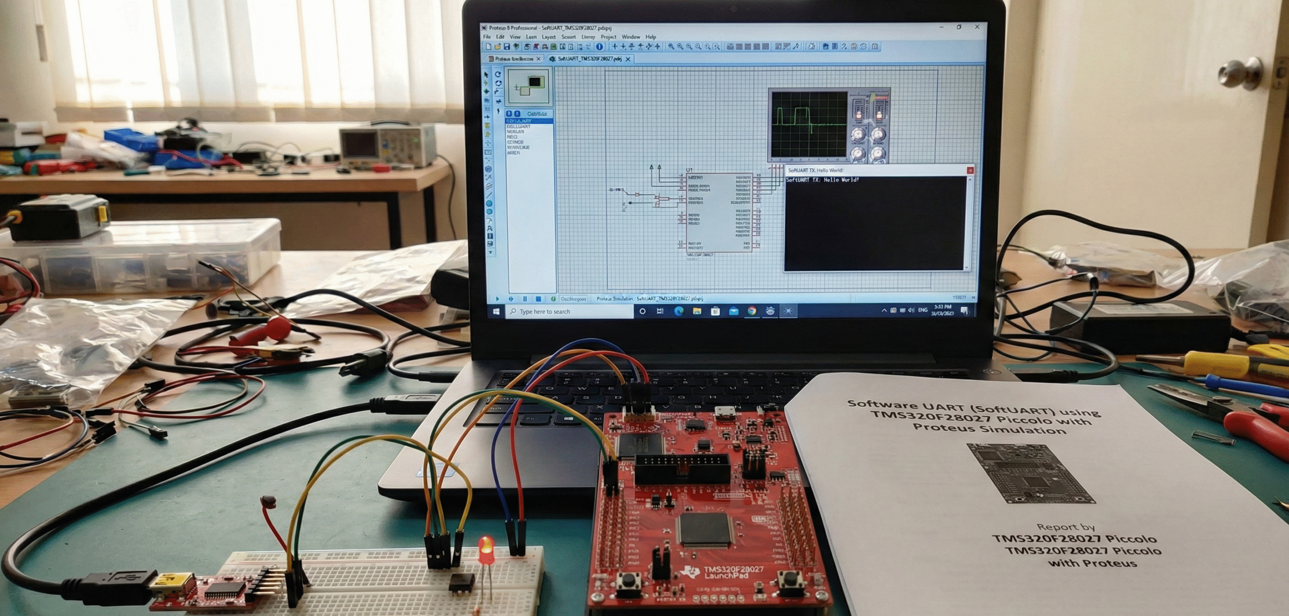
Summary of Software UART (SoftUART) using TMS320F28027 Piccolo with Proteus Simulation


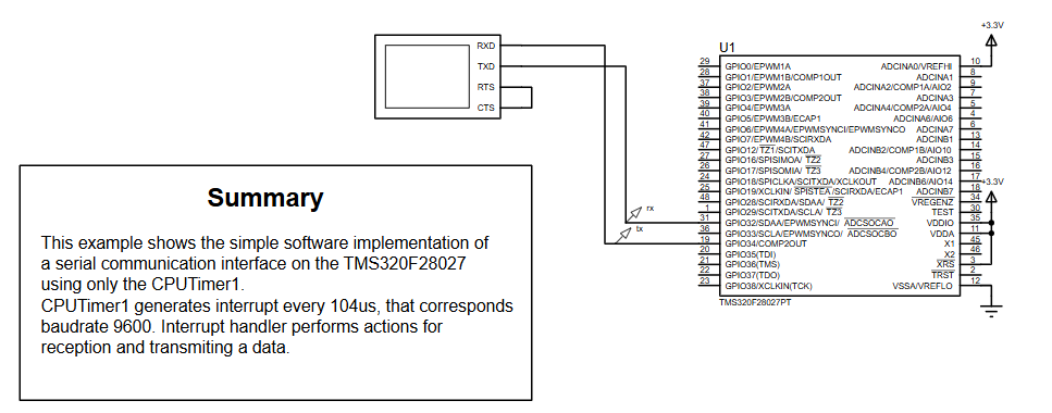
Summary (under 100 words): This SoftUART project implements a 9600‑baud UART entirely in software on the TMS320F28027 Piccolo using CPU Timer1 interrupts and GPIO bit‑banging. It supports transmit and receive (with optional parity), sends "Hello, world!n" at startup, and echoes received characters incremented by one. The design is demonstrated and debugged in Proteus VSM, showcasing timer-driven ISR handling, GPIO configuration, and a practical educational example for embedded systems without hardware UART peripherals.

Parts used in the SoftUART project:

  • TMS320F28027PT Piccolo Microcontroller
  • GPIO32 (configured as UART RX)
  • GPIO34 (configured as UART TX)
  • CPU Timer1 (for 104 µs interrupts / 9600 baud timing)
  • 3.3V power supply
  • Proteus Virtual Terminal (Proteus VSM)
  • TI support libraries: InitSysCtrl, InitPieVectTable, InitCpuTimers, ConfigCpuTimer

Introduction

Creating reliable serial communication without a hardware UART might sound tricky, but this SoftUART project proves how flexible embedded systems can be. In this tutorial-style showcase, we build a software-implemented UART on the TMS320F28027 Piccolo microcontroller and test it inside a realistic Proteus simulation environment. This approach is ideal for learners and engineers exploring digital communication, microcontroller projects, embedded systems, and practical electronics without relying on dedicated UART peripherals.

The project uses CPU Timer1 to generate precise timing for 9600-baud communication and handles both transmit and receive operations entirely in software—making it an excellent educational example of low-level firmware design and timing-critical interfaces.

SoftUART testing using Piccolo LaunchPad
Illustrative View of the Concept.

How the Project Works (Overview)

The core concept behind this SoftUART is simple: instead of using the onboard SCI (Serial Communication Interface), the code manually toggles GPIO pins at the correct bit rate using high-precision timer interrupts. Every 104 microseconds, CPU Timer1 triggers an interrupt—corresponding to 9600 baud—and the firmware processes one UART bit.

Transmit Side:

  • Data is formatted into start bit → 8 data bits (LSB first) → optional parity → stop bit(s).

  • A bit mask shifts through the frame.

  • GPIO34 outputs the appropriate logic level for each bit.

Receive Side:

  • The firmware watches GPIO32 for a falling edge, indicating a start bit.

  • Once reception starts, each interrupt samples the RX pin.

  • After 8 bits (plus optional parity), the byte is stored.

This bit-banging UART technique is highly relevant for DIY electronics, low-pin microcontroller projects, and applications where hardware peripherals are unavailable or reserved for other tasks.

Block Diagram / Workflow Explanation

Although UART is typically hardware-driven, this project replicates its behavior in software using:

  1. CPU Timer1
    Generates precise 104 µs interrupts for bit timing.

  2. GPIO32 (Rx) & GPIO34 (Tx)
    Act as the communication interface.

  3. Transmit Workflow

    • Load character

    • Build frame

    • Shift out bits on each interrupt

  4. Receive Workflow

    • Detect start bit

    • Sample RX line each interrupt

    • Assemble byte in buffer

  5. Application Loop

    • Sends "Hello, world!\n" once

    • Echoes any received character with +1 offset (e.g., ‘A’ → ‘B’)

This structure maps cleanly onto Proteus’ virtual Piccolo model, allowing realistic simulation of GPIO activity.

Key Features of This Project

  • Full software UART (SoftUART) — no SCI hardware required
  • Runs at 9600 baud using precise timer interrupts
  • Bidirectional communication (TX and RX)
  • Simple bit-banging logic ideal for learning UART fundamentals
  • Works on TMS320F28027 Piccolo, a common DSP-oriented microcontroller
  • Clean and modular C code for portability
  • Complete Proteus VSM simulation support
  • Demonstrates GPIO configuration, timers, interrupts, and embedded state machines

Components Used

Based on the schematic and firmware:

  • TMS320F28027PT Piccolo Microcontroller

  • GPIO32 – UART RX

  • GPIO34 – UART TX

  • CPU Timer1 – Core of timing engine

  • Power supply (3.3V)

  • Virtual terminal (Proteus)

  • Supporting TI libraries:

    • Clock system (InitSysCtrl)

    • PIE interrupt mapping (InitPieVectTable)

    • Timer driver (InitCpuTimers, ConfigCpuTimer)

Applications

This kind of software UART system is useful in:

  • Low-cost embedded systems without hardware UART

  • Debugging channels in DSP-based systems

  • Bootloader communication

  • Interfacing with simple modules (Bluetooth HC-05, RS-232 converters, etc.)

  • Educational projects demonstrating UART timing and bit-level control

  • Simulation-driven prototyping when hardware is unavailable

Explanation of the Code (High-Level)

Here’s a readable breakdown of the main modules in the SoftUART firmware:

1. Initialization

  • Configures GPIO32 as input (RX) and GPIO34 as output (TX).

  • Enables pull-ups and asynchronous qualification for proper UART behavior.

  • Sets up Timer1 interrupt at 104 μs using ConfigCpuTimer().

2. UART Transmission (send_char)

  • Builds full UART frame (start → data → optional parity → stop).

  • Initializes mask and activates TX context.

  • ISR shifts out one bit at each interrupt.

3. UART Reception

  • Detects start bit when RX goes low.

  • Samples RX pin every timer tick.

  • Stores received byte and flags readiness.

4. Main Application

  • Sends "Hello, world!\n" on startup.

  • Waits for received characters.

  • Echoes back received character + 1 (simple transformation).

5. Timer1 ISR

Handles both TX and RX roles:

  • Transmitter: Drives GPIO34 depending on current bit.

  • Receiver: Samples GPIO32 and assembles bits.

  • Detects when frame ends and refreshes contexts.

This ISR-driven design ensures accurate timing regardless of main-loop workload

Source Code

Download
#include "DSP28x_Project.h"     // Device Headerfile and Examples Include File
#define STOPMASK   0x0800
#define DTMASKBITS (1 << STOPMASK) - 1
#define NBITS  8

struct CONTEXT
 { unsigned short dt;
   unsigned short mask;
   char active;
   char dtrdy;
   char has_parity;        // 0 - no parity, 1 - odd, 2 - even
 } rxcontext, txcontext;

interrupt void cpu_timer1_isr(void);

Proteus Simulation Behavior

In Proteus VSM:

  • The TMS320F28027 model runs the firmware exactly as on hardware.

  • GPIO34 toggles according to UART TX activity.

  • A Virtual Terminal window displays "Hello, world!" when the simulation starts.

  • Typing characters into the terminal triggers the RX flow—the MCU responds by sending back the next ASCII character.

This lets learners visualize UART timing, observe GPIO toggling, and debug embedded systems without touching real hardware.

(FAQs)

1. Does this project use the hardware UART of the TMS320F28027?

No — all TX/RX operations are implemented in software using GPIO pins and timer interrupts.

CPUTimer1 triggers every 104 µs, ensuring precise timing for each UART bit at 9600 bps.

Yes. Modify the timer period in ConfigCpuTimer() and adjust bit timing accordingly.

UART idle line state is high, so TX must start in that condition.

Partially. It is interrupt-driven and can handle simple full-duplex communication.

It’s a basic demonstration showing that RX works and TX responds dynamically.


Yes — as long as timing and GPIO assignments match.

Connect GPIO32/34 to a Virtual Terminal and run the simulation.

Yes — the code supports odd/even parity via has_parity.

Check timer settings, interrupt frequency, and wiring in Proteus.

Conclusion

This project is a solid hands-on example of how embedded systems can emulate hardware behavior entirely in software. By combining bit-level UART framing, precise timer interrupts, and Proteus simulation, you get a deep understanding of communication protocols while building practical electronics skills.

Whether you’re learning DSP-based microcontrollers or exploring DIY electronics, this SoftUART implementation on the TMS320F28027 Piccolo is a valuable addition to your microcontroller project arsenal.

Quick Solutions to Questions related to the SoftUART project:

  • Does this project use the hardware UART of the TMS320F28027?
    No — all TX and RX operations are implemented in software using GPIO pins and timer interrupts.
  • How is baud rate accuracy achieved without hardware UART?
    CPU Timer1 triggers every 104 microseconds, providing precise timing for each UART bit at 9600 baud.
  • Can I change the baud rate?
    Yes. Modify the timer period in ConfigCpuTimer and adjust bit timing accordingly.
  • Why is GPIO34 initially set to logic HIGH?
    UART idle line state is high, so TX must start in that condition.
  • Can this SoftUART send and receive at the same time?
    Partially. It is interrupt-driven and can handle simple full-duplex communication.
  • Why does the main loop echo back character plus 1?
    It is a basic demonstration showing that RX works and TX responds dynamically by sending the next ASCII character.
  • Can this firmware run on real hardware?
    Yes — as long as timing and GPIO assignments match the hardware setup.
  • How do I test this in Proteus?
    Connect GPIO32 and GPIO34 to a Virtual Terminal and run the simulation; the terminal shows Hello, world! and accepts input to trigger RX flow.
  • Can parity be enabled?
    Yes — the code supports odd or even parity via the has_parity field.
  • What if characters appear corrupted?
    Check timer settings, interrupt frequency, and wiring in Proteus.

About The Author

Ibrar Ayyub

I am an experienced technical writer holding a Master's degree in computer science from BZU Multan, Pakistan University. With a background spanning various industries, particularly in home automation and engineering, I have honed my skills in crafting clear and concise content. Proficient in leveraging infographics and diagrams, I strive to simplify complex concepts for readers. My strength lies in thorough research and presenting information in a structured and logical format.

Follow Us:
LinkedinTwitter