Summary of USB 0-500MHz RF Power Meter with AD8307 using pic microcontoller
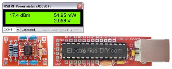
This article details the construction and specifications of an AD8307 USB RF Power Meter capable of measuring frequencies from 0 to 500MHz. The device utilizes a PIC18F2550 microcontroller and an AD8307 IC to convert analog signals into digital data displayed on a PC via USB software. It supports auto-ranging measurements from 1nW to 2W, extendable to 50W with an external attenuator, and draws power directly from the USB port.
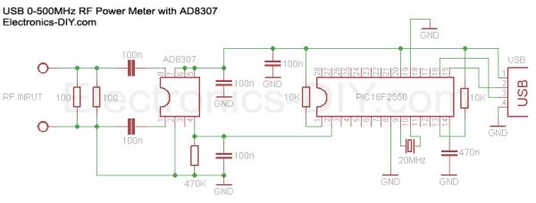
Parts used in the AD8307 USB 0-500MHz RF Power Meter:
- PIC18F2550 Programmed Microcontroller
- AD8307 RF Power Meter IC
- RF Power Meter Probe PCB
- USB IO Board PCB
- USB Type B Connector
- 20MHz Crystal Resonator
- 470K Resistor
- 10K Resistors (2x)
- 100 Resistors (2x)
- 470nF Ceramic Capacitor
- 100nF Ceramic Capacitors (5x)
|
|
 AD8307 USB 0-500MHz RF Power Meter
 USB IO Board
 USB IO Board is used to sample voltage from AD8307 chip and pass the information in a digital format to a PC via USB port. The board consists of very few components; mainly PIC18F2550 microcontroller, standard USB Type B connector, breadboard compatibille PCB, 20MHz crystal resonator, two capacitors and two resistors.
- What is the frequency range of this RF power meter?
The device measures transmitter RF power at a frequency input of 0 to 500MHz. - How does the meter connect to a computer for display?
The meter connects to a PC via a USB port to display measurements using specific software instead of an LCD module. - Can this project measure RF power higher than 2W?
Yes, it can measure up to 50W by adding a simple 10-40dBm resistor attenuator. - How is the AD8307 probe powered?
The probe is self-powered by drawing power from the USB port through the USB IO Board. - What components are primarily found on the USB IO Board?
The board consists mainly of a PIC18F2550 microcontroller, a USB Type B connector, a 20MHz crystal resonator, two capacitors, and two resistors. - Does the meter support auto-ranging measurements?
Yes, it features auto-range RF wattage measurement across nW, uW, mW, and W ranges. - What unit of measurement does the output display use?
Output is displayed in dBm, Watts, and input voltage. - How is the probe connected to the main board?
The AD8307 probe connects to the USB IO Board using a three-wire cable.