
Summary of PIC 3x3x3 LED cube
This project builds a 3x3x3 LED cube driven directly by a PIC16F628A microcontroller with minimal extra components. It covers making the controller board, assembling LED grids into layers, creating a detachable base for the cube, programming the PIC with provided HEX, and finishing details like mounting bolts and heatsinking the 7805 regulator. The cube displays patterns controlled by the PIC and is presented as a beginner-friendly first microcontroller project.
Parts used in the 3x3x3 LED cube:
- PIC16F628A microcontroller
- 27 diffused LEDs
- 7805 voltage regulator
- 9 330 ohm resistors
- 12 male headers
- 12 female headers
- 18-pin DIP IC socket
- Controller circuit board (homemade)
- Cube base circuit board (homemade)
- 16V 100uF electrolytic capacitor
- 100nF ceramic capacitor
- Plug and small heatsink
- PCB mounting bolts
- Ribbon cable (optional)
Here´s my 3x3x3 LED cube, it’s controlled by a PIC16F628A microcontroller.
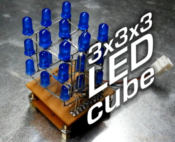
This is my first microcontroller project that finally works, so i suppose is not that difficult to make for beginners.
I hope you’ll enjoy that instructable and even make your own LED cube!
Step 1: Materials
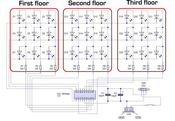
The PIC drives the cube without external IC’s and with very few extra components.
To make your own LED cube you’ll need:
-A PIC16F628A Microchip microcontroller ($2 ebay)


-27 diffused LEDs ($3.50 50pcs ebay)
-7805 voltage regulator ($0.99 3pcs ebay)
-9 330ohm resistors ($1.14 ebay)
-12 male + 12 female headers ($2.59 ebay)
-18 pin DIP IC socket ($0.99 10pcs ebay)
-Controller and cube circuit boards (make them yourself)
-16v 100uF electrolytic capacitor (recycled from old boards)
-100nF ceramic capacitor (recycled from old boards)
-Plug and small heatsink (recycled from old boards)
Step 2: The controller

First, make the controller board (instructions here), drill the holes and tin the pads carefully.
Place all the components as shown in the picture and solder them in place.
Step 3: The cube

Mark a 3×3 1 inch grid in a corck and hole the places for the LEDs, this will keep them aligned while you bend and solder the leads.
Place them diagonally so the leads won’t touch, solder the cathodes to one side and then bend the anodes above the cathodes. Solder the anodes 90º away from the cathodes.
Repeat the process to make two more grids and place them on each other making anodes and cathodes be in the same side.
Bend the 9 protuding cathodes down and solder them in 3 columns.
I’ve bent the 9 anodes so they came arranged in three groups of three, you can simply solder a ribbon cable, but it won’t hold the cube up as a structure.
Step 4: The Base

To plug the cube in the controller i made a base board.
It’s useful for unplugging the whole cube from the controller board so you can access to the microcontroller and stract it for re-programming.
Use the circuit stencil to make your own board.
If you prepared you cube like mine, you have to solder the heathers, insert the cube in the PCB holes and solder it from upside.
Make sure the cube module fits in the controller board.
Step 5: Programming

Time to program the microcontroller!
Open your favourite programming program,
plug your PIC into the programmer,
choose the file ”LED cube HEX” and upload it,
configure the right fuses
and program your microcontroller.
More programs can be made for different light patterns, but i don’t know how to do easily.
If you know how to do it, how make your own patterns, please, tell me.
Step 6: Final Details
As finishing details i added four PCB mounting bolts to make it stand on them, that will avoid short-circuits if the cube is placed on a metal surface.
You’ll also need to connect the cube to a power supply so solder a plug cable in the input pads.
I noticed that the lm7805 i trimmed off was overheating when i use a 12v power supply due to the input and output voltage difference.
It couldn’t sink all that heat with the small surface i let, so i cutted a small piece of aluminium heatsink and i thermally-glued it to the voltage regulator.
Step 7: Enjoy It
The cube is finished and working, it looks great and does not overheat at all.
There may be bigger, more coloured and brighter cubes, but i’m proud of how my first LED cube looks and works.
I hope you enjoyed that instructable and even made your own cube.
IF you liked this project, please vote it for the make it glow and microcontroller contests
And don’t forget to ask your doubts!
Source : PIC 3x3x3 LED cube
- What microcontroller is used in the project?
The project uses a PIC16F628A microcontroller. - How many LEDs are needed for the cube?
The cube requires 27 diffused LEDs arranged in a 3x3x3 grid. - Does the design use external driver ICs?
No, the PIC drives the cube without external ICs. - What components are needed for power regulation?
A 7805 voltage regulator, a 16V 100uF electrolytic capacitor, and a 100nF ceramic capacitor are used. - How are the LED layers assembled?
Each layer is made on a 3x3 grid; cathodes are soldered to one side and anodes bent and soldered 90 degrees away, then three layers are stacked aligning anodes and cathodes. - How is the cube connected to the controller?
A detachable base board with headers is made so the cube plugs into the controller and can be removed for reprogramming. - How is the PIC programmed?
Use a PIC programmer, insert the PIC, choose the provided LED cube HEX file, configure fuses, and upload the HEX to program the microcontroller. - What was done to prevent the 7805 from overheating?
A small piece of aluminium heatsink was glued thermally to the 7805 to help dissipate heat when using a 12V supply.
