Summary of PWM DC Motor Controller for PIC12F683
This project is a PWM DC motor/power controller built around a PIC12F683. It uses the PIC CCP peripheral to generate PWM that drives an N-channel logic-level MOSFET in a low-side configuration. An ADC input (typically from a variable resistor) sets duty cycle via a configurable lookup table mapping input values to duty and one of three fixed PWM periods. A push button cycles mapping tables (persisted in EEPROM), an LED shows the selection, and a digital input can force output off (0% duty).
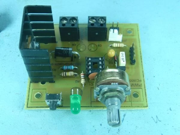
Parts used in the PWM DC Motor Controller:
- PIC12F683 microcontroller
- N-channel logic-level MOSFET (low-side switch)
- Variable resistor (potentiometer) for ADC input
- Push button for cycling mapping tables
- LED to indicate current mapping/table
- Digital control input (pull-down to disable output)
- EEPROM (onboard PIC EEPROM used for saving table selection)
- Power supply and supporting passive components (resistors, capacitors)
- PCB or protoboard for assembly
Description
There are lots of designs on the Internet for DC power controllers using Pulse Width Modulation (PWM) to control the speed of a motor or power to a resistive load. Most of these use analogue methods to generate the PWM signal which in turn drives a power MOSFET or transistor.
When I wanted a speed controller for the PCB drill I use to make all my PIC Projects what else could I do but design a PWM Power Controller around a PIC – a practical PIC project for sure.
I came up with a fairly straightforward design based on a PIC12F683 using the Capture/Compare/PWM
(CCP) peripheral inside the PIC to generate a PWM output. An ‘N’ Channel Logic Level MOSFET in a low side configuration is driven by the PIC to control the output power to the motor.
A variable resistor provides a voltage input to the PIC which is converted to a digital value using the onboard Analogue to Digital convertor, this in turn is used to set the PWM duty cycle. Since the PWM duty cycle is adjusted using a voltage signal input to the PIC it is possible to use an alternative analogue front-end instead of VR1 to provide this voltage input and therefore control of the duty cycle.
In the original version of this project the input from the Analogue to Digital Converter (ADC) was fed directly to the duty cycle register of the PWM module on the PIC, therefore the PWM output duty changed linearly in direct proportion to the change in input voltage to the ADC; much the same as an analogue PWM. The switch input allowed the PWM period to be selected in one of three ranges; 15.6Khz, 3.8Khz and 980Hz.
The significant feature in the new version of the firmware which sets it apart from analogue PWM is that it now uses the input from the ADC as an index to a data table. This table contains the required output duty cycle and period. By creating a suitable table of data you can map any value at the input of the ADC to any duty cycle and one of 3 fixed periods at the PWM output.
The switch input now cycles through 3 mapping tables. The default tables supplied with the code have a one-to-one mapping of input voltage to duty cycle output and fixed periods of 15.6Khz, 3.8Khz and 980Hz respectively to keep it backward compatible with the original version of the code.
More details of this and example map table files can be found in the Operation section.
A push button cycles through three different mapping tables. The mapping table in use is saved to EEPROM so it always powers up using the last selected table; an LED indicates the current setting.
There is also a digital control input that allows the output driver to be turned off. When pulled low the PWM output is set to 0%.
For more detail: PWM DC Motor Controller for PIC12F683
- What microcontroller is used in the project?
The project uses a PIC12F683 microcontroller. - How is the PWM generated?
The PWM is generated using the PIC12F683 Capture/Compare/PWM peripheral. - Can the duty cycle be controlled by an analogue input?
Yes, a variable resistor provides a voltage to the PIC ADC which sets the duty cycle via a lookup table. - Does the controller support different PWM frequencies?
Yes, three fixed PWM periods are available: 15.6 kHz, 3.8 kHz, and 980 Hz. - How are input values mapped to duty cycle and period?
The firmware uses the ADC input as an index into a data table that maps input values to duty cycle and one of three periods. - Can the mapping table be changed during operation?
Yes, a push button cycles through three mapping tables and the selection is saved to EEPROM. - Is there a way to disable the PWM output digitally?
Yes, a digital control input when pulled low forces the PWM output to 0% duty. - Does the controller retain the selected table after power down?
Yes, the selected mapping table is saved to EEPROM so it powers up with the last selected table.