
Summary of Bluetooth Wireless Voltage Meter using PIC12F683 microcontroller
This tutorial shows how to send voltage readings from a PIC microcontroller to a PC via a Wiimote by wiring the PIC to Wiimote button pads, using the PIC ADC to produce 10-bit values, and transmitting those values as simulated button presses. On the PC AutoIt scripts and a Wiimote library receive and decode the data; example PIC code and AutoIt scripts are provided.
Parts used in the Bluetooth Wireless Voltage Meter:
- Wiimote (genuine recommended)
- Transistors 2N3904 or any general purpose NPN (quantity 11)
- Resistors 470K (390K to 560K will work) (quantity 11)
- PIC microcontrollers (examples): PIC12F683-I/P or PIC12F675-I/P (2)
- PIC microcontrollers (example): PIC16F616-I/P (2)
- 5V supply for the PIC chip
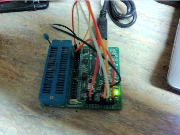
- Pic chip programmer (e.g., Enhanced PICKit 2)
- Breadboard and jumper wires
- Soldering iron and solder
- Voltmeter
- Triwing screwdriver for Wiimote
- PC with Bluetooth
Bluetooth Wireless Voltage Meter using Wiimote + Pic Chip + AutoIt
In this tutorial I’m going to be showing you how you can send voltage values to your pc using a Pic chip, Wiimote, and Autoit3 scripting language. The process works by wiring a pic chip to the button pads of a wiimote. Then using the pic chips Analog to Digital Converter, we obtain a 10bit binary value. We will then send that value to Autoit in the form of button presses using the wiimote as a data interface. On the PC side we will use a library I wrote to receive the data from the wiimote. The library is basically just a port to Wiiuse by Michael Laforest set up in a way to make scripting with the wiimote very easy.
Most pic chips are equiped with multiple Analog to Digital channels. This lets us monitor multiple voltages values if we want to. The total amount of channels sampled will depend on different factors like how many channels the chip has. Channels are sampled one at a time so the more voltages you monitor, the less samples per second you get.
How the Analog to Digital Converter works
The pic chip A/D Converter works by comparing the voltage you’re measuring to a known voltage. In our case the known voltage is the voltage supply 5v. The 10bit value measured is a ratio of the pic chips known voltage 10bit value. So for example a sample thats 10bit value is 387, the voltage value would be V = (5v/1024) * 387 which equals 1.89v
Step 1
Experience, Tools and Parts Needed
Experience:
• Basic understanding of electronics. (Ohms law for example..)
• How to use a bread board and voltage meter.
• How to solder.
• A little knowledge of pic chips will help, but is not really required since all the pic chip code for the examples is already written.
Tools:
• Voltmeter
• Triwing Screwdriver for wimote. ($2 on ebay)
• Soldering Iron, solder
• Breadboard and Jumper wires
• Pic Chip Programmer (Im using the “Enhanced PICKit 2”)
• PC with Bluetooth
Parts: ($20 + $1 + $1 + $5 + $7) = $34
• Wiimote – note that while generic wiimotes will work, a genuine wiimote has best compatibility. (< $20)
• Transistors 2N3904 or any General Purpose NPN Qt: 11 ($1)
• Resistor values 470K (390K to 560K will work): Qt: 11 ($1)
• Pic Chips (any of these will work since I have included multiple examples)
– PIC12F683-I/P or PIC12F675-I/P – 2 examples ($1.25)x2
– PIC16F616-I/P – – 2 examples – ($1.10)x2
– shipping for all 4 pic chips ($7)
• 5v supply for the Pic Chip
Step 2
Software
Download and install the following software: (click links to download)
• AutoIt3
• HI-TECH C Compiler for PIC10/12/16 MCUs (Free Lite Version. Registration is required)
• Wiimote ADC.zip (Note: The html link is just an easy way for me to share, update, and track downloads. Open the .html file and a download dialog will display.)
The Wiimote_ADC.zip contains the following:
• WiimoteMT.au3 – Autoit Library used for communicating with the wiimote.
• Wii Pair.exe – used to pair the wiimote to your pc.
• ScitePIC Startup.exe – A custom standalone Scite Editor that I set up just for working with the pic chips. It has options to compile and program the pic chip for you. I will get into how to use those options later.
• 6 AutoIt script examples along with the Pic chip code that goes with each example.
• 4 Pic chip Hi-Tech C example programs. (2 supporting 12F683 and 12F675, 2 supporting 16f616.
Step 3
Pairing the Wiimote
To pair the wiimote to your pc you have two choices. You can either do a temporary pair, or you can do a permanent authenticated pair. The difference between temporary and permanent pairing is that if you power off, or disconnect the wiimote from your pc and the wiimote is not authenticated, the next time you want to connect you will have to do the pairing procedure again. If it is authenticated, your pc will remember the wiimote, and the wiimote will remember your pc. Needless to say i recommend doing a permanent pair.
Permanent Pair:
-Launch Wii Pair.exe (located in Wiimote_ADC.zip)
-Press the sync button on the wiimote located under the battery cover. The leds on wiimote will begin flashing.
-Press Easy Pair button.
– When the wiimote has been successfully paired you will see the address of your wiimote in the list and Connected, Remembered and Authenticated will all say true. Once it has verified that the wiimote is authenticated it will launch a wiimote example.
– NOTE: IF at any time during the pairing process the wiimotes leds stop flashing, PRESS THE SYNC BUTTON AGAIN.
Temporary Pair:
-Go into your bluetooth panel and select “add a new device”. Press the sync button. When it asks you about the pairing code, select the option to pair without using a code.
For more detail: Bluetooth Wireless Voltage Meter using PIC12F683 microcontroller
- How does the PIC ADC convert voltage to a value?
The PIC ADC compares the measured voltage to the reference supply (5V) and produces a 10-bit value where V = (5V/1024) * ADC_value as explained in the article. - Can multiple voltages be monitored at once?
Yes, many PIC chips have multiple ADC channels, but channels are sampled one at a time so more channels reduce samples per second. - What software is required on the PC?
AutoIt3, Scite4AutoIt3, HI-TECH C Compiler for PIC10/12/16 MCUs, and the Wiimote_ADC.zip package provided in the tutorial. - How do you pair the Wiimote permanently?
Use Wii Pair.exe, press the Wiimote sync button, press Easy Pair, and confirm Connected, Remembered and Authenticated are true. - What is the difference between temporary and permanent pairing?
Temporary pairing requires re-pairing after power off; permanent authenticated pairing lets the PC and Wiimote remember each other so reconnection is automatic. - How is the ADC data sent to the PC?
The PIC sends the 10-bit ADC value to the PC in the form of simulated Wiimote button presses; an AutoIt Wiimote library receives and decodes the data. - Are example codes provided for PIC and AutoIt?
Yes, the Wiimote_ADC.zip contains AutoIt scripts, PIC Hi-Tech C example programs, and related files. - What tools are recommended for building this project?
Voltmeter, triwing screwdriver for the Wiimote, soldering iron, breadboard and jumper wires, and a PIC programmer are recommended.
