
Summary of Low cost temperature data logger using PIC and Processing
This project implements a low-cost PC-based digital thermometer and data logger using a PIC12F1822 microcontroller and an MCP9701A temperature sensor. The system reads ambient temperature, converts it via the microcontroller's ADC, and transmits data to a PC through a USB-UART interface for real-time display and ASCII file logging using the Processing platform.
Parts used in the Low Cost Temperature Data Logger:
- PIC12F1822 microcontroller
- MCP9701A temperature sensor
- USB-UART module
- PC with Processing software
This project describes an easy and inexpensive way of adding a digital thermometer and data logging feature to a PC. It involves a PIC microcontroller that gets the surrounding temperature information from the Microchip MCP9701 sensor, and sends it to a PC through an USB-UART interface. The USB port of the PC is also used to power the device. The open-source Processing programming platform is used to develop a PC application that displays the temperature in a graphics window on the computer screen. The PC application also records the temperature samples plus date and time stamps on an ASCII file.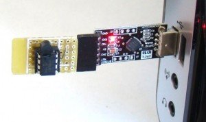
This project is based on Microchip’s PIC12F1822 microcontroller from the enhanced mid-range PIC family. It has got 8-pins in total and the power supply voltage range of 1.8V to 5.5V. The microcontroller has four 10-bit ADC channels and one Enhanced Universal Synchronous Asynchronous Receiver Transmitter (EUSART) module for serial communication. The temperature sensor used here is MCP9701A, which is a Low-Power Linear Active Thermistor IC from Microchip Technology. The range of temperature measurement is from -40°C to +125°C. The output voltage of the sensor is directly proportional to the measured temperature and is calibrated to a slope of 19.53mV/°C. It has a DC offset of 400mV, which corresponds to 0°C. The offset allows reading negative temperatures without the need for a negative supply. The output of the sensor is fed to one of the ADC channels of the PIC12F1822 microcontroller for A/D conversion. The internal fixed voltage reference (FVR) module is configured to generate a stable 2.048 V reference voltage for A/D conversion. The use of FVR module ensures the accuracy of the A/D conversion even when the supply voltage is not stable. The PIC12F1822 microcontroller then serially transmits the 10-bit ADC output to a PC.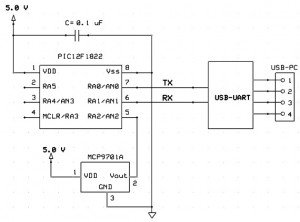
The circuit diagram of this project is pretty simple. The microcontroller reads the temperature sensor’s output through RA2/AN2 pin and convert it to a 10-bit digital number. The Tx (RA0) and Rx (RA1) port of the EUSART module are connected to the corresponding pins of the USB-UART module.
For more detail: Low cost temperature data logger using PIC and Processing
- How does the system power the device?
The USB port of the PC is used to power the device. - What programming platform is used for the PC application?
The open-source Processing programming platform is used to develop the PC application. - Does the sensor support negative temperatures?
Yes, the DC offset of 400mV allows reading negative temperatures without a negative supply. - What is the measurement range of the MCP9701A sensor?
The range of temperature measurement is from -40°C to +125°C. - How is A/D conversion accuracy ensured?
The internal fixed voltage reference module generates a stable 2.048 V reference voltage. - What format is used to record temperature data on the PC?
The application records samples plus date and time stamps on an ASCII file. - Which pins connect the EUSART module to the USB-UART module?
The Tx (RA0) and Rx (RA1) ports are connected to the corresponding pins of the USB-UART module. - What is the slope calibration of the sensor output voltage?
The output is calibrated to a slope of 19.53mV/°C.

