Summary of RFID Reader – Access Control System
This article describes a simple RFID access control system using a PIC12F1822 microcontroller operating at 16MHz. It supports two modes: standalone operation with relay unlocking or PC connectivity via RS232 for data logging and management. The system reads H10301 format cards, stores up to 64 IDs, and allows programming through button sequences or serial commands.
Parts used in the RFID Access Control System:
- PIC12F1822 microcontroller
- Antenna coil L1 (approx. 80 turns)
- Magnet wire (0.2 mm diameter)
- C11 capacitor (tuned for resonance)
- C4 capacitor
- C6 component (voltage reference point)
- R7 resistor
- Green LED
- Red LED
- Relay
- Push-button switch (BUT)
- J2 connector
This device is a simple access control system which uses RFID cards. It is designed with PIC12F1822 microcontroller running on internal oscillator at 16MHz. It generates 125 KHz carrier frequency and decodes the respond data stream – format H10301- FSK modulation 26 bits only. These cards (made by HID and other companies) are widely used in US.
The device can work in two modes:
1 – Stand alone RFID access system – J2 (BUT) is open when power is applied.
2 – RFID reader connected to a computer – J2 (BUT) is shorted when power is applied.
To switch between modes you need to remove power, switch BUT and reapply power. The condition of BUT is checked only once in the beginning of the program.
Stand alone RFID access system
Apply a card near antenna L1. The unit reads it and makes a short beep. If the card (facility code and card number) match any card stored in the memory green LED comes on and relay energized for 3 seconds (door is unlocked), otherwise red LED blinks 4 times.
The newly programmed microcontroller does not have any cards stored in its memory. The first card it reads saves in memory and become administrator’s card.
To add more cards (microcontroller can store up to 64 cards including administrator’s card) execute this sequence:
1 – read administrator’s card
2 – when green LED is on press BUT (short J2)
3 – release BUT – green LED should stay on, if not – start again from 1
4 – read card you want to add – it saves and the green LED goes off
To delete card from memory:
1 – press BUT and hold it
2 – read administrator’s card
3 – when green LED comes on, release BUT – green LED should stay on, if not start again from 1
4 – read card you want to delete – it deletes it from the memory and green LED goes off
If you do not have the card (lost, stolen ets.) to delete it connect the unit to the computer.
RFID reader connected to a computer
Read cards and sends information (facility code and card number) to PC in hex format. The connection is RS232 at 57600 baud rate with TTL levels. I use a USB to RS232 TTL converter cable (they are cheap and there is a lots to sell on eBay) and terminal program like http://sites.google.com/site/terminalbpp/
The read card information shows like:
67 89AB where 67 is facility code (hex) and 89AB is card number (hex).
In this mode you can see a list of all cards saved in the memory. To get this list send a command FF, and it will return something like:
00: 12 3456
01: 78 9ABC
…………..
Where 00:, 01:,….. are consecutive numbers of cards. If you want to delete a card, send it consecutive number to the device. If you delete card 00: (administrator’s card) all cards will be deleted too.
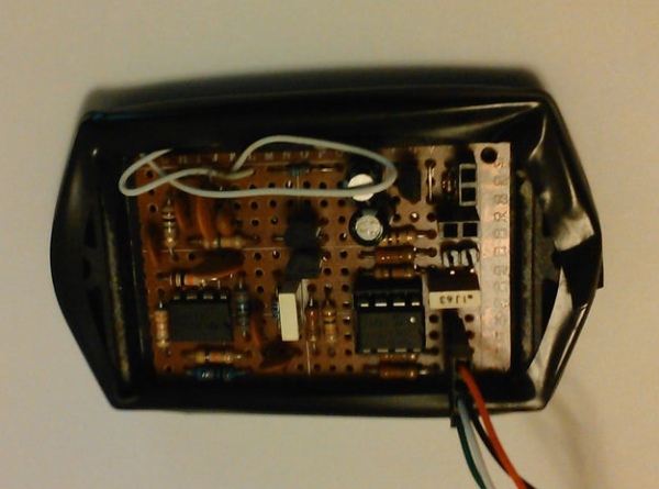
The antenna coil has about 80 turns with magnet wire diameter 0.2 mm, and size 70 X 50 mm. number of turns, wire diameter and size of antenna are not critical. If you use small diameter of wire and resistance of antenna coil become high (10 ohms and more) R7 should be 0 ohms. More important is L1, C4 and C11 to be in resonance at 125 kHz. This may be achieved by selection of C11 so that on C6 you have 20V or more.
The coil is under black electrical tape.
Attachments
Source: RFID Reader – Access Control System
- How do I switch between standalone and computer modes?
Remove power, toggle the BUT switch, and reapply power; the mode is determined by the state of BUT at startup. - What happens when a valid card is read in standalone mode?
The green LED turns on, the relay energizes for 3 seconds to unlock the door, and a short beep sounds. - Can the device store more than one card?
Yes, it can store up to 64 cards including the administrator's card after the first card is programmed as admin. - How do I add a new card to the memory?
Read the administrator card, press and release BUT while the green LED is on, then read the new card to save it. - What is the procedure to delete a card from memory?
Hold the BUT, read the administrator card, release BUT when the green LED lights up, then read the card you wish to delete. - How can I manage cards if the administrator card is lost?
Connect the unit to a computer via RS232 to delete cards using serial commands since physical deletion requires the admin card. - What format does the device send to the computer?
It sends facility code and card number in hex format over RS232 at 57600 baud rate with TTL levels. - How do I list all saved cards via the computer?
Send the command FF to the device, which returns a list of consecutive card numbers and their codes. - Does the antenna coil size matter critically?
No, the number of turns, wire diameter, and size are not critical as long as the components resonate at 125 kHz. - What adjustment is needed if the antenna resistance is high?
If resistance exceeds 10 ohms, R7 should be set to 0 ohms to ensure proper operation.