Summary of Wireless Communication Using Cheap 433MHz RF Modules and Pic Microcontrollers. Part 2
This article details the second part of a wireless communication project using 433MHz RF modules and PIC microcontrollers. It upgrades the transmitter to use sleep modes with watchdog timers and adds preamble bytes for gain adjustment, while the receiver integrates a PIC16F887 and HD44780 LCD to display data. The system achieves a 20-meter range through walls at 1200 or 2400 baud rates.
Parts used in the Wireless Communication Project:
- PIC12F1822 microcontroller
- PIC16F887 microcontroller
- TX/RX 433MHz RF modules
- USB to UART TTL cable adapter
- 16x2 character LCD (HD44780)
- 10uF decoupling tantalum capacitor
- 10K trimmer
- 220 Ω 1/4 W resistor
- 1 KΩ 1/4 W resistor
- Antenna 433Mhz,3dbi
On the first part of this instructable, I demonstrated how to program a PIC12F1822 using MPLAB IDE and XC8 compiler, to send a simple string wirelessly using cheap TX/RX 433MHz modules.
The receiver module was connected via a USB to UART TTL cable adapter to a PC, and the data received were displayed on RealTerm. The communication was performed at 1200 baud and the maximum range achieved was about 20 meters through walls. My tests showed that for applications where there is no need for high data rate and long range,and for continuous transmission, these modules performed exceptionally well.
The second part of this project demonstrates how to add a PIC16F887 microcontroller and a 16×2 character LCD module on the receiver. Moreover, on the transmitter, a simple protocol is followed with the addition of a few preample bytes. These bytes are necessary for the RX module to adjust its gain prior to getting the actual payload. At the receiver side,the PIC is responsible of getting and validating the data which are displayed on the LCD screen.
Step 1: Transmitter Modifications
On the first part, the transmitter was sending a simple string every few ms using eight data bits, a start, and a stop bit at 1200 bits per second. As the transmission was almost continuous, the receiver had no trouble adjusting it’s gain to the received data. On the second part, the firmware is modified so that the transmission is performed every 2.3 seconds. This is achieved using the watchdog timer interrupt (set to 2.3s) to wake up the microcontroller, which is put in sleep mode in between each transmission.
In order for the receiver to have time to fine-tune it’s gain, a few preamble bytes with short LO times “(0Xf8)(0Xf8)(0Xf8)(0Xf8)(0Xf8)(0Xfa)” are send before the actual data. Payload is then indicated by a start ‘&’ and a stop ‘*’ byte.
Hence, the simple protocol is described as follows:
(0Xf8)(0Xf8)(0Xf8)(0Xf8)(0Xf8)(0Xfa)&Hello InstWorld!*
Moreover, a 10uF decoupling tantalum capacitor is added between RF module’s V+ and GND to get rid of the ripple caused by the dc-dc step up module.
Baud rate remained the same, yet my tests showed that at 2400 baud also, the transmission was efficient.
Attachments
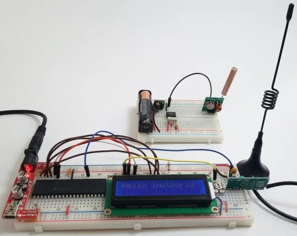
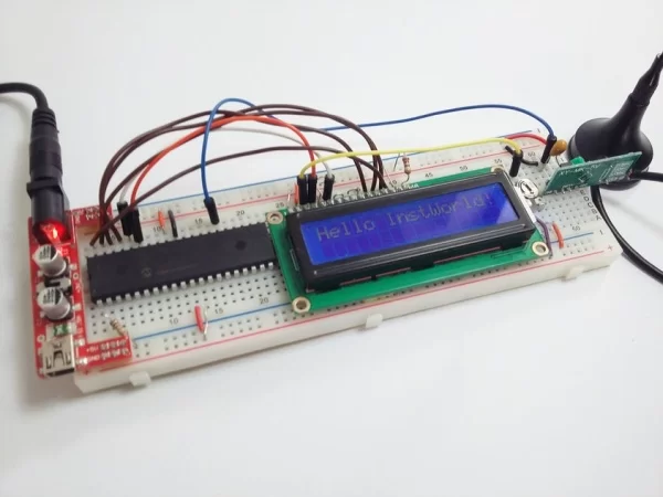
Step 2: Receiver Modifications: Adding PIC16F887 and HD44780 LCD
The receiver design was based on PIC16F887, but you can use a different PIC with little modifications.
In my project I used this 40 pin μC, as I will need extra pins for future projects based on this design. The output of the RF module is connected to the UART rx pin, whereas a 16×2 character lcd (HD44780) is connected through PORTB pins b2-b7 to display the received data.
As with Part 1, the data received are also displayed on RealTerm. This is achieved using UART tx pin which is connected via a USB to UART TTL cable adapter to a PC.
Looking into the firmware, when a UART interrupt takes place, the program checks whether the byte received is a start byte (‘&’). If yes, it starts recording the subsequent bytes, until a stop byte is caught (‘*’). As soon as the whole sentence is obtained, and if it conforms to the simple protocol described before, it is then sent to the lcd screen, as well as to the UART tx port.
Prior to receiving the start byte, the receiver has already adjusted its gain using the preceding preamble bytes. These are critical for the smooth operation of the receiver. A simple overrun and framing error check is performed, however this is only a basic UART error handling implementation.
In terms of hardware, a few parts are needed for the receiver:
1 x PIC16F887
1 x HD44780
1 x RF Rx module 433Mhz
1 x 10 μF tantalum capacitor (decoupling)
1 x 10 K trimmer (LCD font brightness)
1 x 220 Ω 1/4 W resistor (LCD backlight)
1 x 1 KΩ 1/4 W
1 x Antenna 433Mhz,3dbi
In practice, the received worked exceptionally well in ranges up to 20 meters though walls.
Attachments
Step 3: A Few References…
There are many blogs on the web giving tips on PIC programming and troubleshooting besides the official Microschip website. I found the following very helpful:
Step 4: Conclusions and Future Work
I hope this instructable helped you understand how to use RF modules and Pic microcontrollers. You can adjust your firmware to your own needs and include CRC and encryption. If you want to make your design even more sophisticated, you may utilize Microschip’s Keeloq technology.
In case your application needs bi-directional data, you would need to have a pair of TX/RX at both microcontrollers, or you can use more sophisticated transceiver modules. However, using this kind of cheap 433MHz modules, only half duplex communication can be accomplished. Further to this, in order to make the communication more reliable your would need to have some form of handshaking between TX and RX.
On the next instructable, I will show you a practical application where an environmental sensor with temperature, barometric pressure and humidity is added on the transmitter. Here, the transmitted data will include crc and will have a basic encryption.
The sensor will be using the i2c port of the PIC12F1822, whereas the implementation of both transmitter and receiver will be exposed through schematics and pcb files.
Thanks for reading me!
Source: Wireless Communication Using Cheap 433MHz RF Modules and Pic Microcontrollers. Part 2
- How does the transmitter conserve power?
The firmware uses the watchdog timer interrupt set to 2.3 seconds to wake the microcontroller from sleep mode before each transmission. - What is the purpose of the preamble bytes?
Preamble bytes are sent before the actual data to allow the receiver module time to adjust its gain prior to receiving the payload. - Does the baud rate affect the transmission efficiency?
Tests showed that the transmission remains efficient at both 1200 baud and 2400 baud rates. - Can I use a different microcontroller for the receiver?
Yes, the design is based on the PIC16F887 but can be adapted to use a different PIC with minor modifications. - What components are required for the receiver hardware?
The receiver requires a PIC16F887, HD44780 LCD, 433Mhz RF Rx module, capacitors, resistors, a trimmer, and an antenna. - How is the received data validated?
The program checks for a start byte and a stop byte, then validates the data against the simple protocol before displaying it. - What is the maximum range achieved in tests?
The system worked exceptionally well with ranges up to 20 meters even through walls. - Can this setup support bi-directional communication?
No, cheap 433MHz modules only support half duplex communication; bi-directional data requires a pair of TX/RX units or transceiver modules.