


Summary of PIC16F84 ADVANCED TIMER CIRCUIT
The article describes a PIC16F84-based advanced timer circuit capable of setting intervals from 2 minutes 45 seconds to 3 minutes 45 seconds using five relays. The system uses tactile switches on PORTA to set time, lights an LED upon activation, and triggers a buzzer with Morse code-like patterns after the relay cycle completes. It utilizes a 2SC1815 transistor for relay control and mentions potential timing errors due to RC oscillators at varying temperatures, suggesting crystal oscillators for stability.Parts used in the Advanced Timer Circuit:
- PIC16F84 microcontroller
- Five relays
- Tactile switches (Tact SW)
- 10KΩ pull-up resistors
- LEDs
- Speaker/Buzzer
- 2SC1815 transistors
- RC oscillator or Crystal oscillator
PIC16F84 made a beginning with a simple timer in the introduction to electronic. 2 minutes 45 seconds every 15 seconds to 3 minutes and 45 seconds set in five relays to switch the unit ON. Hours after the relay... Electronics Projects, PIC16F84 Advanced Timer Circuit "microchip projects, microcontroller projects, pic assembly example, pic16f84 projects,
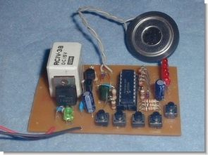
PIC16F84 made a beginning with a simple timer in the introduction to electronic. 2 minutes 45 seconds every 15 seconds to 3 minutes and 45 seconds set in five relays to switch the unit ON. Hours after the relay is set at the buzzer OFF will also be informed. This has been called in to help make the call letters of his match with the length of Morse from playful buzzer. Morse meet to look like I’m going to be easy to rewrite software. I set the time switch is pressed which we can see the LED. Time error, we used the RC oscillator clock, and the room temperature (temperature in the lower frequency) in a few seconds. I want to ceramic or crystal oscillator.
LED, SOUND OPERATED SIMPLE TIMER CIRCUIT
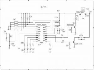
It is to put it with a pull-up resistor of 10KΩ setting switch time (tact SW) to each of PORTA BIT but, PIC will examine whether the ON and which switch first. After detecting a switch that is turned ON, and then ON also BIT7 of PORTB at the same time as the LED light corresponding. I ON the relay that is attached to the transistor 2SC1815 by it. After you (OFF the relay and LED) OFF, it will sound the speaker ON, OFF repeatedly at the 2SC1815 BIT6 This time the PORTB set time has passed.
The fine adjustment of the set time, you can by rewriting the number of 50msec (CNT50M). The clock frequency is also stable time at the same time a stable room temperature is stabilized.
FILE DOWNLOAD LINK LIST (in TXT format): LINKS-5235.zip
Source: PIC16F84 ADVANCED TIMER CIRCUIT
Quick Solutions to Questions related to Advanced Timer Circuit:
- How is the time range configured?
The time is set between 2 minutes 45 seconds and 3 minutes 45 seconds by pressing switches corresponding to five relays. - What component detects the switch input?
The PIC examines whether the switches connected to PORTA BIT are turned ON first. - Which transistor controls the relay operation?
A transistor labeled 2SC1815 is attached to the relay to switch it ON or OFF. - How does the system indicate the end of the set time?
After the relay turns OFF, the speaker sounds repeatedly while the LED turns OFF. - Can the set time be fine-tuned?
Yes, fine adjustment is possible by rewriting the number associated with 50msec (CNT50M). - What causes timing errors in this circuit?
Using an RC oscillator clock can cause frequency shifts due to room temperature changes. - What is recommended for stable timekeeping?
It is suggested to use a ceramic or crystal oscillator instead of an RC oscillator. - How is the buzzer behavior described?
The buzzer plays letters matching the length of Morse code to inform when the time has passed.
Related projects
PIC Stepper Motor Controller using PIC16F84A with Proteus Simulation
Introduction Stepper motors are widely used in embedded systems and DIY electronics projects where precise position control is required. This PIC Stepper...
Programmers & ICSP · PIC16F84APIC Musical Doorbell using PIC16F84A with Proteus Simulation
IntroductionThis microcontroller project demonstrates a musical doorbell built around a PIC16F84A and a simple piezo sounder.Using two push buttons, the system allows...
Beginner Tutorials · PIC16C84Exploring the World of PIC Microcontrollers: An Architectural Overview
A Peripheral Interface Microcontroller (PIC), developed by General Instruments Microcontrollers in 1993, operates under software control and is programmed to execute various...
Clocks & TimersAdaptive Alarm Clock: Build a Smart, User-Centric wake-Up system
Project Overview The goal of this ambitious undergraduate project was to develop a novel alarm clock capable of analyzing a person's unique...
Clocks & TimersDesigning Your Ideal Alarm Clock: An Introduction to PIC18
Within this laboratory session, you'll employ the C language to create an alarm clock, delving into the implementation of "C" programs on...
Clocks & TimersBuilding your Dream Alarm Clock Using the PIC18
Objective: In this laboratory session, your objective is to create an alarm clock using the C programming language. You will gain proficiency...

Muhammad Bilal
I am a highly skilled and motivated individual with a Master's degree in Computer Science. I have extensive experience in technical writing and a deep understanding of SEO practices.