


Summary of PIC16F628A LINE FOLLOWING ROBOT PROJECT
This article describes a DIY line-following robot project centered on the PIC16F628A microcontroller. It highlights the use of CNY70 sensors for path detection and an L298 motor driver for controlling the engine, powered by an upgraded battery. The project includes downloadable source code and PCB assembly files to assist hobbyists in building their own robots.Parts used in the PIC16F628A Line Following Robot:
- PIC16F628A Microcontroller
- CNY70 Detection Sensor
- L298 Motor Driver
- Line Following Robot Control Board
- Powerful Battery
- Engine/Motor
Line following robot project with a more powerful battery and the engine was a good guess but it can result in opportunities, folks have the best hand made based on PIC16F628A circuit used for the detection sensor CNY70 L298... Electronics Projects, PIC16F628A Line following robot project "microchip projects, microcontroller projects, pic assembly example, pic16f628 projects,
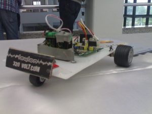
Line following robot project with a more powerful battery and the engine was a good guess but it can result in opportunities, folks have the best hand made based on PIC16F628A circuit used for the detection sensor CNY70 L298 used for motor control
LINE FOLLOWING ROBOT CONTROL BOARD
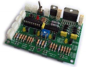
PIC16F628A Line following robot project pcb pic assembly source code
FILE DOWNLOAD LINK LIST (in TXT format): LINKS-1378.zip
Source: PIC16F628A LINE FOLLOWING ROBOT PROJECT
Quick Solutions to Questions related to PIC16F628A Line Following Robot:
-
What microcontroller is used in this line following robot?
The project uses the PIC16F628A microcontroller. -
Which sensor is used for detection in this circuit?
The CNY70 sensor is used for detection. -
What component is used for motor control?
The L298 is used for motor control. -
Can I download the source code and PCB files?
Yes, a file download link list in TXT format named LINKS-1378.zip is available. -
Is there a video tutorial for this project?
Yes, an embedded YouTube video link is provided for the project. -
Does this project involve a custom control board?
Yes, the project features a dedicated Line Following Robot Control Board.
Related projects
DHT11 Low Cost Humidity Sensor using PIC16F628A with Proteus Simulation
IntroductionThis microcontroller project demonstrates how to interface a low-cost DHT11 temperature and humidity sensor with a PIC16F628A using a Proteus simulation environment.The...
LCD & Display Projects · PIC16F628AFrequency Counter by PIC16F628
In this project we are building a basic and low cost frequency counter circuit . It can measure from 16Hz to 100Hz...
Games, Toys & Calculators · PIC16F628ATIC TAC TOE game using PIC16F628
This project is not to introduce Tic Tac Toe. Everyone knows this game. It's to introduce two features. Bi-coloured LEDs, microcontrollers and...
Motors & RoboticsReal-Time CAN-Based Vehicle Monitoring System with PIC MCU
INTRODUCTION The Controller Area Network (CAN) is a robust vehicle communication bus standard that was primarily developed for automobile applications but has...
Motors & RoboticsEasy Way to Learn Robotics Using Microcontrollers: A Beginner’s Guide
The title, "Easy Way to Learn Robotics Using Microcontrollers," promises an accessible entry point for those curious about the exciting world of...
Motors & Robotics · PIC16F877AEfficient Sun-Following Robot: A Solar Tracker with Microcontroller Control
Abstract The impending global challenge of dwindling non-renewable fuel resources underscores the urgency of transitioning towards renewable energy alternatives like solar power....

Muhammad Bilal
I am a highly skilled and motivated individual with a Master's degree in Computer Science. I have extensive experience in technical writing and a deep understanding of SEO practices.