


Summary of A PIC16F819 DYMOCLOCK
This project is a simple LED clock and thermometer built around a PIC16F819 (18-pin) using direct LED driving (no decoders/drivers), 27 LEDs arranged in three rows for hours, minutes/seconds/°C, and fine increments, plus a silicon diode as temperature sensor. It runs a 12-hour clock with 2°C thermometer resolution, multiplexed LED tables, and button controls for mode, toggle, and set; compiled with mikroC for a PIC16F819 at 16 MHz.Parts used in the Simple LED clock with thermometer:
- PIC16F819 microcontroller (18-pin)
- 16 MHz crystal
- 27 LEDs (25 mA each)
- Silicon diode used as temperature sensor
- Push buttons (mode, toggle/advance, set)
- Colored hookup wires for LED wiring
- Power supply (suitable for PIC and LEDs)
- Miscellaneous PCB or protoboard and wiring hardware
- built around a little 18 pins PIC
- no 7 segment display, only LEDs
- no decoder, no buffer, no driver for the LED display
- a cheap temperature sensor
The solution of direct LED driving comes from a Microchip Application Note AN234, and as I'm using 25 mA LEDs, I simply removed all current limiting resistors.
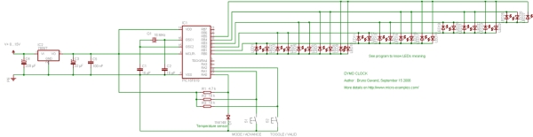
 A silicon diode is used as temperature sensor, and the rest of the circuit is very classic around a PIC16F819 :
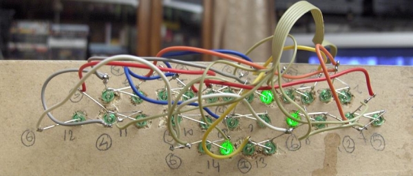
some colored wires are helpful !
See the source code for LED numbering.
 { 0, 22, 21, 25, 26,
- What microcontroller is used in the project?
The project uses a PIC16F819 microcontroller. - How many LEDs are used for the display?
The display uses 27 LEDs arranged in three rows. - Does the design use LED drivers or decoders?
No, the design drives LEDs directly without decoders, buffers, or drivers. - What component is used as the temperature sensor?
A silicon diode is used as the temperature sensor. - What clock format and thermometer resolution does the project implement?
It implements a 12-hour clock and a thermometer with 2°C resolution. - What compiler and clock speed are specified for the PIC?
The source is compiled with mikroC and targets a PIC running at 16 MHz. - Are current limiting resistors used for the LEDs?
No, current limiting resistors were removed because 25 mA LEDs and Microchip AN234 direct drive technique are used. - How are different display modes selected?
Buttons on PORTA are used: one for mode/advance and one for toggle/validate; both together act as set.
Related projects
Cooking Timer using PIC16F819 microcontroller
Cooking Timer This is a school project but I thought it can be fun to all of you cooking people out there,...
Meters & Test Instruments · PIC16F819Digital Measuring Tape
I always was thinking of a measuring tape that never ends and be able to measure very long things. So I decided...
Motors & Robotics · PIC16F819ELECTRIC BIKE MOTOR CONTROL CIRCUIT TC4420 PWM PIC16F819
Motor control circuit PWM method used PIC16F819 output microchip product tc4420 high speed 6 amp mosfet driver used MOSFETs, the two pieces...
LED ProjectsAn Application-Driven Microcontroller Curriculum
Understanding how to apply microcontrollers lies at the core of modern embedded systems education. This student project takes an experiential approach to...
LED ProjectsBuild this microcontroller controlled rainbow flying disc – and then throw it!
Hello all and welcome to this super simple and inexpensive instructable. If you like throwing frisbees AND you like flashing lights AND...
LED ProjectsLED Scrolling Display Project Working With Circuit Diagram
We normally use a simple static LED display screen to convey a message. Earlier, when we want to display large data, we...

Ibrar Ayyub
I am an experienced technical writer holding a Master's degree in computer science from BZU Multan, Pakistan University. With a background spanning various industries, particularly in home automation and engineering, I have honed my skills in crafting clear and concise content. Proficient in leveraging infographics and diagrams, I strive to simplify complex concepts for readers. My strength lies in thorough...