Motor control circuit PWM method used PIC16F819 output microchip product tc4420 high speed 6 amp mosfet driver used MOSFETs, the two pieces irf2907 also switched MOSFETs current drawn to detect tlv2461 op amp made with 0.01ohm shunt resistor current… Electronics Projects, Electric Bike Motor Control Circuit TC4420 PWM PIC16F819 “microchip projects, microcontroller projects, pwm circuits,
Motor control circuit PWM method used PIC16F819 output microchip product tc4420 high speed 6 amp mosfet driver used MOSFETs, the two pieces irf2907 also switched MOSFETs current drawn to detect tlv2461 op amp made with 0.01ohm shunt resistor current through the sensing circuit there. PWM motor driver pcb project’s source code pic-c, schematic files.

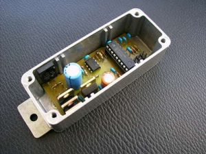
PWM ELECTRONIC BIKE MOTOR DRIVER
The heart of the controller is a PIC microcontroller, the PIC16F819 It has internally everything we will need, including a PWM output, and analog inputs. it is very economical.
The is based on a standard linear regulator LM7805. A zener diode is responsible for lower input voltage, as the regulator would not accept directly from the battery 36V (42V even when it is loaded block)
Measuring the battery voltage is done through a simple voltage divider by 10 and an analog input of the PIC.
Source: chaenel.free.fr Electric Bike Motor Control Circuit pcb schematic pic c source code alternative link:
FILE DOWNLOAD LINK LIST (in TXT format): LINKS-2228.zip
Source: ELECTRIC BIKE MOTOR CONTROL CIRCUIT TC4420 PWM PIC16F819