I always was thinking of a measuring tape that never ends and be able to measure very long things. So I decided to make a small odometer and use it as a digital measuring tape.
I used a PIC16F819 microcontroller and a sensor from an old computer mouse (the remaining parts of one of my other projects Crazy Mouse) to make this simple measuring tape.
Do you want to make yourself? If yes read the rest of this instructable.
Step 1: What You Need
To make this measuring tape you need the following components and tools:
- Printed circuits (find files in the next step)
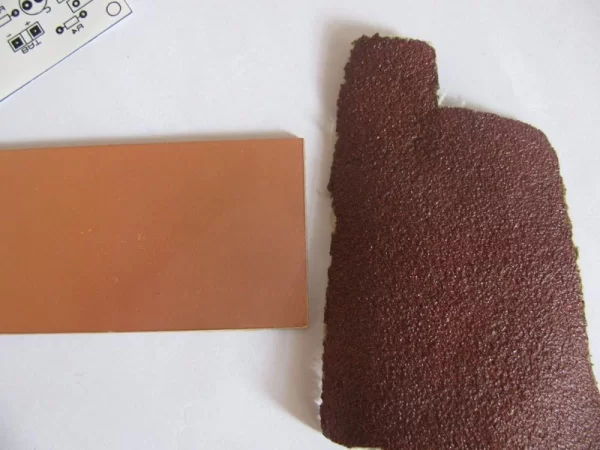
- Copper board
- Sandpaper
- Iron
- Circuit board acid
- 1mm drill
- Soldering tools
- 1x PIC16F819 microcontroller + socket
- An old mouse (or one of its IR shaft encoders)
- 3x BC547 transistors
- 3x common anode 7 segments
- 1x 100uF electrolyte capacitor
- 1x 470ohm resistor (1/8 watt)
- 7x 10k resistors (1/8 watt)
- 2x Simple push buttons
- 1x Simple switch
- 2x AA batteries with a battery holder
- 1x Wheel (+ maybe some gears)
- A box for this measuring tape
Step 2: Making the PCB
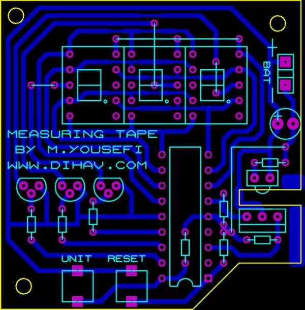
First you need to make a PCB. Here is a good instructable for making PCBs.
- Print the circuit on a glossy paper with a laser printer without scaling.
- Cut some copper board and clear it with sandpaper.
- Put the printed circuit on it.
- Press the hot iron on the board.
- Remove the papers.
- Soak boards in acid and wait till visible copper disappears.
- Wash the boards.
- Drill the holes.
- Clear the board with sandpaper.
Attachments
Step 3: Soldering Components
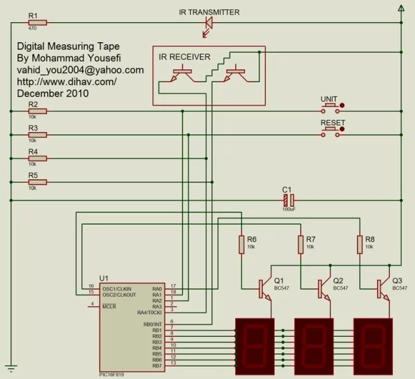
Now it’s time to solder components on the board. Here is a good instructable for Soldering.
- Solder the mouse IR transmitter and receiver on the board.
- Solder 470ohm resistor behind the IR transmitter.
- Solder 10k resistors on the board.
- Solder some wires on the lines that connect two holes together. (jumpers)
- Solder microcontroller socket on the board in a correct direction.
- Solder seven segments.
- Solder transistors.
- Solder buttons with some wire.
- Solder the capacitor on the board in a correct direction.
- At last solder the switch to the battery holder and solder its wires to the BAT terminal.
Step 4: Programming
Download the following file and program your PIC16F819 microcontroller. You can use any programmer to do this, I am using WinPic with a JDM programmer. After programming your microcontroller place it on its socket on the board.
Don’t forget to:
- Set oscillator to internal RC
- Set RA6 port to I/O port
- Turn off all timers
- Set MCLR to input pin
- Turn off the brown out detect
In other words: config word ($2007) = 0x3F18
Attachments
Step 5: Attach the Wheel
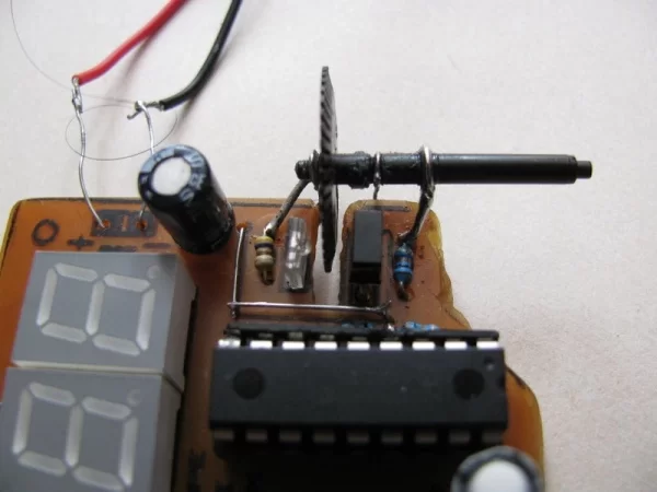
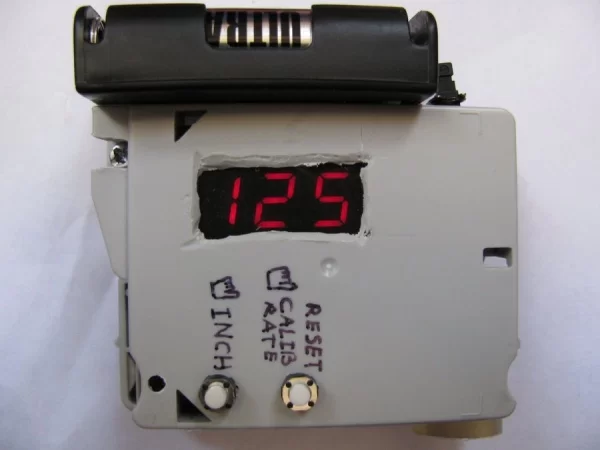
Solder two legs on the board to hold the shaft encoder wheel, turn on the measuring tape and adjust the position of the toothed wheel. Rotating the wheel must cause increase in displaying number and rotating it back must cause decrease in displaying number. Finally attach a wheel to the toothed wheel shaft directly or using some gears, and put all in a box.
Step 6: How It Works?
The IR receiver component contains two IR receivers that the sequence of their state change indicates the direction of rotation (00 10 11 01 00 … and 00 01 11 10 00 …).
One of the IR receivers is connected to A4 pin and the other is connected to B0 pin. Every time the state of B0 pin changes from 0 to 1 the microcontroller increases or decreases the “Ticks” variable depend on the state of A4 pin, high A4 indicates forward rotation and low A4 indicates backward rotation:
void interrupt(void)
{
if (INTCON.INTF)
{
if (Sensor1)
{
if (RButton)
{
if (OneMeterTicks == MaxOneMeterTicks) OneMeterTicks = 0;
OneMeterTicks++;
}
else
Ticks++;
}
else
{
if (RButton)
{
OneMeterTicks–;
if (OneMeterTicks == 0) OneMeterTicks = MaxOneMeterTicks;
}
else
Ticks–;
}
if (abs(Ticks) >= OneMeterTicks * 10) Ticks = 0;
INTCON.INTF = 0;
}
}
The number of ticks made by the change of B0 pin state determines the distance traveled after scaling by factor “OneMeterTicks”. The value of “OneMeterTicks” can be changed by rotating the wheel while holding down the “RESET” button.
if (Ticks < 0)
n = -Ticks;
else
n = Ticks;
n *= 100;
if (UButton == 1)
n /= (unsigned long int)(OneMeterTicks * 2.54); // inch
else
n /= (unsigned long int)OneMeterTicks; // cm
Digit[2] = n / 100;
n = n % 100;
Digit[1] = n / 10;
Digit[0] = n % 10;
I used “mikroC PRO for PIC” to write the program.
Attachments
Step 7: Calibration
- Turn on the device.
- Move it gently through a line that you know its length.
- Hold the “RESET” button down and rotate the wheel to see correct number on the display.
- Release the “RESET” button.
- The device is now calibrated.
Step 8: How to Use

- Turn on the device.
- Move it on a line gently to measure the distance traveled.
- Press the “RESET” button to set display number to zero.
- Hold down “INCH” button to see the display number in inches.
Source: Digital Measuring Tape