


Summary of PIC 16f877 microcontroller based RPM Meter
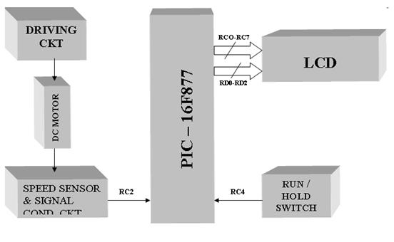
The project builds an RPM meter using a PIC16F877 microcontroller to measure DC motor speed. A speed sensor’s conditioned pulses feed Timer1 (TMR1/RC2) as external clock; counts over one second are multiplied by 60 to get RPM. Operation has RUN (measure each second) and HOLD (display previous value) modes toggled by a pushbutton (RC4). Results and mode are shown on an LCD (data RC0–RC7, control RD0–RD2). Timer0 provides 1/16 s time slices via interrupts. Motor, driver, sensor, and signal-conditioning circuits are external.Parts used in the RPM meter:
- PIC16F877 microcontroller
- Speed sensor (tachometer or pulse sensor)
- Signal-conditioning circuit for sensor pulses
- DC motor (external)
- DC motor driver circuit (external)
- 16x2 or similar LCD display
- Push button switch for Run/Hold (connected to RC4)
- Supporting passive components (resistors, capacitors)
- Power supply for microcontroller and motor
- Crystal or clock source for PIC (implied from code timing)
AIM :
INTERFACING:
- Pulses from speed sensor connected to TMR1 clock input-RC2
- Run/Hold push button switch connected to –RC4
- Data lines connected to Port C - RC0: RC7
- Control lines connected to Port D - RD0: RD2
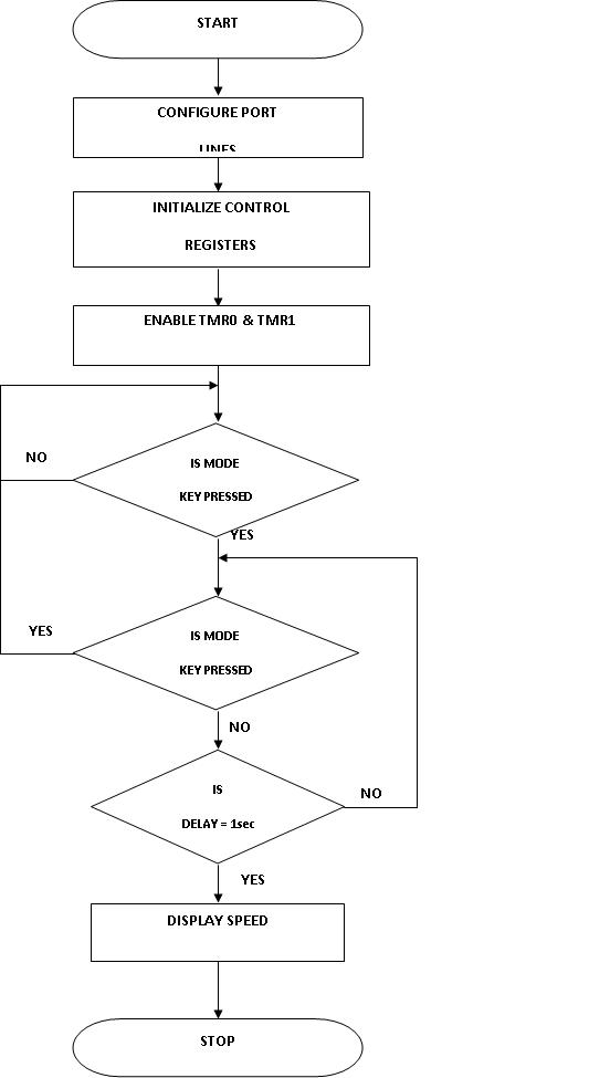
- Timer0 used for generating time slice of 1/16 sec in interrupt driven mode
- By default meter will be in HOLD mode with display ‘00’.
- Mode of operation and the speed are displayed on LCD
 MAIN CLRF CCP1CON ; CCP Module is off
For more detail: PIC 16f877 microcontroller based RPM Meter
Quick Solutions to Questions related to the RPM meter:
- How is motor speed measured?
Speed sensor pulses, after signal conditioning, are fed to Timer1 as an external clock; the Timer1 count for one second is multiplied by 60 to obtain RPM. - Which microcontroller is used?
The PIC16F877 microcontroller is used. - How are RUN and HOLD modes selected?
A push button connected to RC4 toggles between RUN and HOLD modes on each press. - Where is the speed displayed?
The speed and mode are displayed on an LCD connected with data lines on RC0–RC7 and control lines on RD0–RD2. - Which pin receives sensor pulses?
Pulses from the speed sensor are connected to the Timer1 clock input at RC2 (TMR1). - What does HOLD mode do?
HOLD mode displays the previous measured speed value; by default the meter shows 00 in HOLD. - How is timing for measurement provided?
Timer0 is used to generate 1/16 second time slices in an interrupt-driven mode to manage timing. - Is signal conditioning required?
Yes, the speed sensor output must be signal conditioned before connecting to Timer1; a signal-conditioning circuit is provided externally. - What initial configuration is done in code?
The code clears and configures TMR1, CCP, interrupt flags, and sets CCP capture mode and T1CON for Timer1 with a 1:8 prescaler.
Related projects
PIC16F877 Driving LCD in 4-Bit Mode using PIC16F877 with Proteus Simulation
Introduction This microcontroller project shows how a PIC16F877 can drive an LCD display using 4-bit mode inside a Proteus simulation.The project demonstrates...
Programmers & ICSP · PIC16F877AEPE PIC/LCD Demo using PIC16F877 with Proteus Simulation
IntroductionThe EPE PIC/LCD Demo is a classic microcontroller project that demonstrates how a PIC16F877 can fully control a PG12864F graphical LCD.Designed as...
Motors & Robotics · PIC16F877AEfficient Sun-Following Robot: A Solar Tracker with Microcontroller Control
Abstract The impending global challenge of dwindling non-renewable fuel resources underscores the urgency of transitioning towards renewable energy alternatives like solar power....
Meters & Test Instruments · PIC16F688Determine capacitance by measuring the charging time using PIC16F688
When TEST botton is pressed, RA3 pin is set to "1". R2 and R3 are divide the voltage to 1/2 Vra3 which...
Meters & Test InstrumentsFrequency Meter Using Microcontroller
This tutorial simply states how to calculate frequency of a pulse source using a microcontroller. Story https://youtu.be/NAoj-HLRIro This tutorial simply states how...
Meters & Test Instruments · PIC16F84ADigital thermometer with PIC16F84 circuit
This electronic project is a very simple thermometer that is based on the PIC16F84A microcontroller, designed by Microchip. Why to use a...

Ibrar Ayyub
I am an experienced technical writer holding a Master's degree in computer science from BZU Multan, Pakistan University. With a background spanning various industries, particularly in home automation and engineering, I have honed my skills in crafting clear and concise content. Proficient in leveraging infographics and diagrams, I strive to simplify complex concepts for readers. My strength lies in thorough...