


Summary of 89C51 DIGITAL CLOCK CIRCUIT
This article describes an 89C51-based digital clock circuit using a common anode 7-segment display driven by a 7447 decoder. The system utilizes Port0 for data, Port2 with transistors for multiplexing displays, and Port3 buttons for setting hours, minutes, and alarms.Parts used in the 89C51 Digital Clock:
- 89C51 Microcontroller
- 7447 Decoder IC
- Common Anode 7-Segment Display
- Transistors
- Push Buttons (for hour, minute, and alarm settings)
- Resistors
- Port0, Port1, Port2, and Port3 I/O pins
From the incoming data encoded in Port0 integrated 7-segment display with 7447 microcontroller integrated ulaşır.7447 binary code from the 7-segment display is used to show. So when it comes to 0000 a, b, c, d, e, f, g edu... Electronics Projects, 89C51 Digital Clock Circuit "8051 example, avr project, keil example, microcontroller projects,
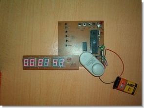
From the incoming data encoded in Port0 integrated 7-segment display with 7447 microcontroller integrated ulaşır.7447 binary code from the 7-segment display is used to show.
So when it comes to 0000 a, b, c, d, e, f, g edu yanmaz.7 segment display LED lights bağlanmıştır.paralel parallel to each other using the same bus to the 7-segment display 7 segment display by selecting different at different times that instant If you have selected to display the data which goes to him.
In practice, common anode 7-segment display is used. Port 2 is connected to the terminals of transistors oval. Transistors display the benefits of riding. that is used to select one of a display. With the help of a single button port3 hour, minute, alarm settings are made.
Port1.0 a alarm fitted. One end of the button being available to the microcontroller used in the other end of the earthing. If the button is not pressed resistance feature is to send a signal to the microcontroller 1. So the trigger button enabled microcontrollers with 0.
89C51 DIGITAL CLOCK SCHEMATIC DIAGRAM
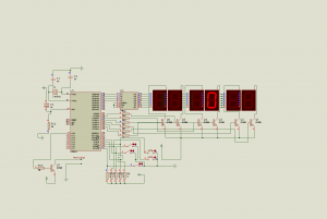
89C51 Digital Clock Circuit keil source code and proteus isis simulation schematic files:
FILE DOWNLOAD LINK LIST (in TXT format): LINKS-4750.zip
Source: 89C51 DIGITAL CLOCK CIRCUIT
Quick Solutions to Questions related to 89C51 Digital Clock:
-
How is the 7-segment display connected to the microcontroller?
Data encoded in Port0 reaches the 7-segment display via the integrated 7447 microcontroller. -
What type of 7-segment display is used in this project?
A common anode 7-segment display is used in practice. -
Which port controls the display selection transistors?
Port 2 is connected to the terminals of the transistors used to select one of the displays. -
How are the time settings adjusted on the clock?
Hour, minute, and alarm settings are made with the help of a single button on Port3. -
How does the alarm trigger mechanism work?
Port1.0 has an alarm button where pressing it sends a signal to enable the microcontroller. -
What happens when binary code 0000 is sent to the display?
The segments a, b, c, d, e, f, and g light up or remain off depending on the specific logic described for that code. -
Where can I find the source code and simulation files?
The keil source code and proteus isis simulation schematic files are available in the LINKS-4750.zip download.
Related projects
Adaptive Alarm Clock: Build a Smart, User-Centric wake-Up system
Project Overview The goal of this ambitious undergraduate project was to develop a novel alarm clock capable of analyzing a person's unique...
Clocks & TimersDesigning Your Ideal Alarm Clock: An Introduction to PIC18
Within this laboratory session, you'll employ the C language to create an alarm clock, delving into the implementation of "C" programs on...
Clocks & TimersBuilding your Dream Alarm Clock Using the PIC18
Objective: In this laboratory session, your objective is to create an alarm clock using the C programming language. You will gain proficiency...
Clocks & TimersBuild a DIY Smart Watch Using Microcontroller
Introduction Wearables (Smart Watch) are becoming increasingly more prevalent in today's markets; however cost continues to limit the demand for such devices....
Clocks & Timers · PIC16F84AIN-8 single nixie tube clock using PIC16F84
After receiving one IN-8 tube from a friend (thanks), I decided to build myself a clock. This clock is more an ornament...
Clocks & Timers · PIC16F84APIC16F84A timer0 code and Proteus simulation
This post provides the timer0 code for PIC16F84A microcontroller. This code is written in C language using MPLAB with HI-TECH C compiler....

Muhammad Bilal
I am a highly skilled and motivated individual with a Master's degree in Computer Science. I have extensive experience in technical writing and a deep understanding of SEO practices.