


Summary of PWM DC Motor Speed Controller Circuit Using PIC16F877A Microcontroller
Summary (under 100 words): This article demonstrates DC motor speed control using PWM with a PIC16F877A microcontroller, driving motors via an L293 H-bridge. It explains why PWM is preferable to series resistors, provides MikroC source code to adjust duty cycle with two switches (S1 increase, S2 decrease) at 1 kHz, and outlines Proteus simulation steps including hex file generation, schematic loading, and running the virtual lab. Downloads and a video walkthrough are referenced.Parts used in the PWM DC Motor Speed Control Project:
- PIC16F877A microcontroller
- L293 motor driver IC (H-bridge)
- DC motor
- Two input switches (S1 and S2)
- Proteus 8 simulation software (for virtual testing)
- MikroC Pro compiler (for generating hex file)
- USB PIC Programmer circuit (for burning PIC, optional practical tool)
- Power supply for motor and PIC
- Wiring and connectors
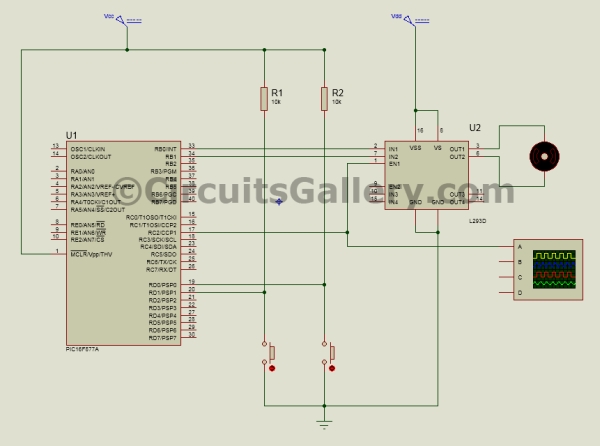
The method of generation of PWM signal is the same as before and this signal is applied to the Enable terminal of L293 motor driver IC. L293 is an H bridge motor controller IC capable of driving 2 Motor loads at a time.
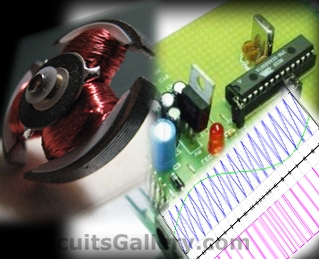 Below is the detailed description of dc motor speed control using PWM technique with Proteus simulation and video demonstration.
Why We Need PWM For Speed Controlling Of DC Motor?
You may wonder why we need PWM signal for controlling DC motor speed when a resistor in series with the motor can simply do this job.
It’s because this method is not recommended in practical and also you don’t get enough torque to drive the motor with the help of resistor.
Limitation of using resistor
- DC motor needs more power during the operation, also it draws more current from the supply.
- If we use resistors, the motor will not get enough power to rotate because some of the power is dropped across the resistor (Low current).
- Also the current will be very low.
 DC Motor Speed Control Using PWM Technique
- With the help of PWM it is possible to control the average power delivered to a load and by thus we can easily regulate the speed of the DC Motor.
- When the width of pulse is high, the motor will rotate with full speed.
- Obviously with low pulse width, speed of motor gets reduced.
- In both cases full current reaches the motor and only the average power changes, thus we get better torque in each case.
- Basically in this method we are chopping the DC voltage at regular interval.
PWM DC Motor Speed Driver Schematic
PIC 16F877A PWM DC Motor Speed Control Mikro C Program
In this Mikro C embedded C program, two input switches are used to control the duty cycle of PWM signal.
S1 for increasing duty cycle and S2 for decreasing the same.
Frequency of PWM signal is set to 1 KHz
void main()
{
short duty1 = 16; //initial value for duty
TRISD = 0xFF; //PORTD as input
TRISC = 0x00; //PORTC as output
TRISB = 0x00; //PORTB as output
PORTB = 0x02; //Run motor in anticlock wise
PWM1_Init(1000); //Initialize PWM1
PWM1_Start(); //start PWM1
PWM1_Set_Duty(duty1); //Set current duty for PWM1
while (1) // endless loop
{
if (PORTD.F0==0) //Checking the button pressed or not
{
Delay_ms(1);
duty1++; // increment duty cycle
PWM1_Set_Duty(duty1); //Change the duty cycle
}
if (PORTD.F1==0) // Checking the button pressed or not
{
Delay_ms(1);
duty1--; // decrement duty cycle
PWM1_Set_Duty(duty1);
}
Delay_ms(10);
}
}
All the program codes are self-explanatory, if you have any doubts please let us know through the comment box below.
PIC PWM Motor Speed Control Simulation in Proteus 8
Let’s start our virtual lab!
Step 1:
Generate .Hex file for PWM speed control in Mikro C.
Compile the above program in Mikro C, if you don't know how to build hex file please read our Getting started guide for Mikro C Pro.
Step 2:
Draw the schematic in Proteus 8 as shown.
Step 3:
Load .Hex file to the PIC.
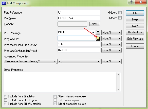
Practical help: Use our USB PIC Programmer circuit for burning PIC Microcontroller practically.
Step 4: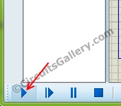 Step 5:
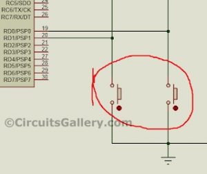
Change duty cycle using provided keys and observe the speed of DC motor (watch the video).
Downloads: PWM DC Motor control .Hex file.
Circuits Gallery Video Lab
Watch this video from our Video lab where I have explained everything related to PIC PWM DC motor speed controller.
[Video will be uploaded soon...]
Please like our Facebook page to stay connected.
Next → Speed and Direction control of DC motor using PIC Microcontroller
For more detail: PWM DC Motor Speed Controller Circuit Using PIC16F877A Microcontroller
Quick Solutions to Questions related to PWM DC Motor Speed Control Project:
- Why use PWM instead of a resistor to control DC motor speed?
The article says resistors drop power and reduce current so the motor won’t get enough torque, while PWM controls average power without reducing instantaneous current. - How does PWM change the motor speed?
The article explains changing pulse width alters the average power delivered; higher pulse width increases speed, lower pulse width reduces speed. - Which microcontroller is used in this project?
The project uses the PIC16F877A microcontroller. - What motor driver IC is used to interface the PIC with the motor?
The article uses the L293 H-bridge motor driver IC to drive the motor. - How are duty cycle adjustments implemented in software?
The Mikro C program reads two input switches S1 and S2: S1 increments duty, S2 decrements duty, and PWM1_Set_Duty updates the duty. - What PWM frequency is used in the example code?
The PWM frequency is initialized to 1 kHz in the code. - How do you test the project virtually?
The article instructs to compile the program to a hex file, draw the schematic in Proteus 8, load the hex into the PIC, and run the simulation while changing duty with keys. - Is a practical programmer suggested for burning the hex file?
The article recommends using their USB PIC Programmer circuit for practical burning of the PIC.
Related projects
PIC16F877 Driving LCD in 4-Bit Mode using PIC16F877 with Proteus Simulation
Introduction This microcontroller project shows how a PIC16F877 can drive an LCD display using 4-bit mode inside a Proteus simulation.The project demonstrates...
Programmers & ICSP · PIC16F877AEPE PIC/LCD Demo using PIC16F877 with Proteus Simulation
IntroductionThe EPE PIC/LCD Demo is a classic microcontroller project that demonstrates how a PIC16F877 can fully control a PG12864F graphical LCD.Designed as...
Motors & Robotics · PIC16F877AEfficient Sun-Following Robot: A Solar Tracker with Microcontroller Control
Abstract The impending global challenge of dwindling non-renewable fuel resources underscores the urgency of transitioning towards renewable energy alternatives like solar power....
Motors & RoboticsReal-Time CAN-Based Vehicle Monitoring System with PIC MCU
INTRODUCTION The Controller Area Network (CAN) is a robust vehicle communication bus standard that was primarily developed for automobile applications but has...
Motors & RoboticsEasy Way to Learn Robotics Using Microcontrollers: A Beginner’s Guide
The title, "Easy Way to Learn Robotics Using Microcontrollers," promises an accessible entry point for those curious about the exciting world of...
Motors & RoboticsInnovative Robotics: A Comprehensive Project Exploration
A DC motor functions as an electromechanical device, translating electrical signals into mechanical movements. The rotation of the motor correlates directly with...

Ibrar Ayyub
I am an experienced technical writer holding a Master's degree in computer science from BZU Multan, Pakistan University. With a background spanning various industries, particularly in home automation and engineering, I have honed my skills in crafting clear and concise content. Proficient in leveraging infographics and diagrams, I strive to simplify complex concepts for readers. My strength lies in thorough...