


Summary of USB 0-500MHz RF Power Meter with AD8307 using pic microcontoller
This article details the construction and specifications of an AD8307 USB RF Power Meter capable of measuring frequencies from 0 to 500MHz. The device utilizes a PIC18F2550 microcontroller and an AD8307 IC to convert analog signals into digital data displayed on a PC via USB software. It supports auto-ranging measurements from 1nW to 2W, extendable to 50W with an external attenuator, and draws power directly from the USB port.Parts used in the AD8307 USB 0-500MHz RF Power Meter:
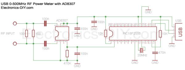
- PIC18F2550 Programmed Microcontroller
- AD8307 RF Power Meter IC
- RF Power Meter Probe PCB
- USB IO Board PCB
- USB Type B Connector
- 20MHz Crystal Resonator
- 470K Resistor
- 10K Resistors (2x)
- 100 Resistors (2x)
- 470nF Ceramic Capacitor
- 100nF Ceramic Capacitors (5x)
|
|
 Measures transmitter RF Power from 1nW to 2W (50W with 40dB attenuator) / -66.6dBm to 33dBm
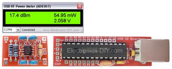 AD8307 USB 0-500MHz RF Power Meter
 USB IO Board
 is used to sample voltage from AD8307 chip and pass the information in a digital format to a PC via USB port. The board consists of very few components; mainly PIC18F2550 microcontroller, standard USB Type B connector, breadboard compatibille PCB, 20MHz crystal resonator, two capacitors and two resistors.
Quick Solutions to Questions related to AD8307 USB 0-500MHz RF Power Meter:
- What is the frequency range of this RF power meter?
The device measures transmitter RF power at a frequency input of 0 to 500MHz. - How does the meter connect to a computer for display?
The meter connects to a PC via a USB port to display measurements using specific software instead of an LCD module. - Can this project measure RF power higher than 2W?
Yes, it can measure up to 50W by adding a simple 10-40dBm resistor attenuator. - How is the AD8307 probe powered?
The probe is self-powered by drawing power from the USB port through the USB IO Board. - What components are primarily found on the USB IO Board?
The board consists mainly of a PIC18F2550 microcontroller, a USB Type B connector, a 20MHz crystal resonator, two capacitors, and two resistors. - Does the meter support auto-ranging measurements?
Yes, it features auto-range RF wattage measurement across nW, uW, mW, and W ranges. - What unit of measurement does the output display use?
Output is displayed in dBm, Watts, and input voltage. - How is the probe connected to the main board?
The AD8307 probe connects to the USB IO Board using a three-wire cable.
Related projects
Pinguino Project: A PIC Microcontroller Based Arduino
This is a complete tutorial to make a PIC Microcontroller based Arduino. This is a complete tutorial to make PIC microcontroller based...
Audio, Sound & Radio · PIC18F2550LM386 based stereo audio amplifier with digital volume control using PIC18F2550
Due to its simplicity (requires minimum external components) and high availability, LM386 is very popular among hobbyists for use in low-voltage audio...
Meters & Test Instruments · PIC18F2550Harmonic Distortion Meter using PIC18F2550
The 3rd harmonic distortion meter has been designed for measuring the quality of AC supply. The meter is built with a PIC18F2550...
Communication & Interfacing · PIC18F4520CAN FD Node based on a PIC18 Microcontroller
The introduction sets the stage for an embedded systems project that involves developing a Embedded C CAN FD project using the MCP2517FD...
Communication & InterfacingLAN9662 Gigabit Switch: Optimized for Industrial Ethernet
Introduction It should come as little surprise therefore that one element of what is now more commonly referred to in some circles...
Communication & InterfacingPIC Microcontroller: Fundamentals & Applications for Students
Introduction Microcontrollers are the key components in the embedded systems market. A variety of embedded systems was formed and developed after the...

Ibrar Ayyub
I am an experienced technical writer holding a Master's degree in computer science from BZU Multan, Pakistan University. With a background spanning various industries, particularly in home automation and engineering, I have honed my skills in crafting clear and concise content. Proficient in leveraging infographics and diagrams, I strive to simplify complex concepts for readers. My strength lies in thorough...