


Summary of PICDEM FS USB CDC Evaluation Board using PIC18F4550 with Proteus Simulation
The PICDEM FS USB CDC Evaluation Board project utilizes the PIC18F4550 microcontroller to demonstrate USB Communication Device Class (CDC) communication via Proteus simulation. It functions as a virtual serial port, allowing real-time data exchange between the microcontroller and a PC without physical hardware. The system integrates user inputs through switches and provides visual feedback via LEDs, making it an ideal educational tool for embedded systems and USB interfacing prototyping.Parts used in the PICDEM FS USB CDC Evaluation Board:
- PIC18F4550 Microcontroller
- USB Connector (USBCONN)
- Clock Source Module (TC77)
- Push Buttons (S1, S2, S3)
- LEDs (D1, D2, D3, D4, D7)
- Resistors (Pull-up and current limiting)
- Virtual Terminal (UART simulation)
- Power Supply & Ground
Introduction
The PICDEM FS USB CDC Evaluation Board is a practical microcontroller project built around the PIC18F4550, designed to demonstrate USB communication using the CDC (Communication Device Class) protocol. This project allows a microcontroller to behave like a virtual serial port when connected to a computer, making data exchange simple and efficient.
Using Proteus simulation, this embedded system can be tested without physical hardware, making it ideal for learning and prototyping. It’s especially useful for developers working in embedded systems, DIY electronics, and USB-based communication projects. The design showcases how USB interfacing can be implemented in real-world applications with minimal external components.
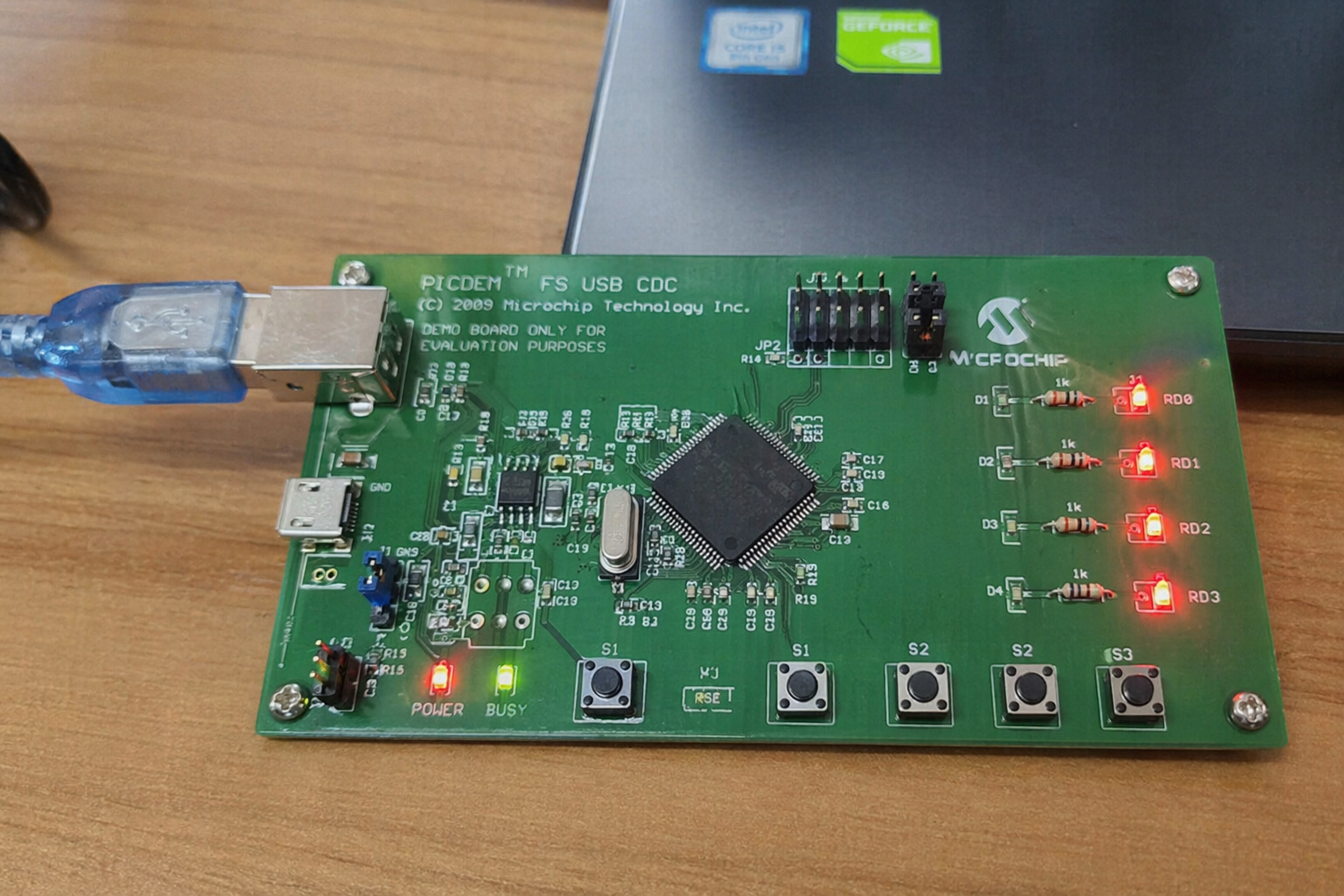
How the Project Works (Overview)
This project uses the PIC18F4550 microcontroller, which has built-in USB support, to establish communication with a PC via USB. The USB module inside the MCU handles enumeration and communication using the CDC protocol.
Inputs from switches and internal signals are processed by the microcontroller, and output is visualized using LEDs. The system can also transmit and receive serial data through a virtual COM port on the PC.
A clock source ensures proper timing, while resistors and passive components stabilize signals and protect the circuit. The USB connector provides both power and communication.
Workflow Explanation
The system can be broken down into the following functional blocks:
- USB Interface (U2): Connects the microcontroller to a PC, enabling USB communication.
- Microcontroller (U1 – PIC18F4550): Core processing unit handling USB protocol and I/O operations.
- Clock Module (U3 – TC77): Provides timing for MCU operations.
- Input Section (S1, S2, S3): Push buttons used for user interaction and control signals.
- Output Section (D1–D4 LEDs): Displays system status or received/transmitted data.
- Serial Interface (Virtual Terminal): Simulates UART communication for debugging and monitoring.
Workflow:
- USB connection is established with the PC.
- PIC18F4550 initializes USB CDC communication.
- Data is transmitted/received via virtual COM port.
- Inputs from switches affect system behavior.
- Output LEDs indicate system status or data activity.
Key Features
- USB CDC (Virtual COM Port) communication support
- Built-in USB module of PIC18F4550 utilized
- Real-time data transmission between MCU and PC
- LED indicators for system feedback
- Multiple user input switches for control
- Fully testable in Proteus simulation
- Serial communication monitoring via virtual terminal
- Reset functionality for system control
Components Used
- PIC18F4550 Microcontroller
- USB Connector (USBCONN)
- Crystal / Clock Source (TC77 module shown)
- Push Buttons (S1, S2, S3)
- LEDs (D1, D2, D3, D4, D7)
- Resistors (Pull-up, current limiting)
- Virtual Terminal (UART simulation)
- Power Supply & Ground
Explanation of Code
The firmware for this project mainly focuses on USB communication and basic I/O handling.
- USB Module: Initializes the USB stack and manages CDC communication.
- UART / Serial Handling: Enables data transmission between MCU and PC via virtual COM port.
- GPIO Control: Reads input from switches and controls LEDs accordingly.
- Interrupt Handling: Manages USB events and communication timing.
- Main Loop Logic: Continuously checks for incoming data and updates outputs.
The code ensures seamless communication between the embedded system and the host PC.
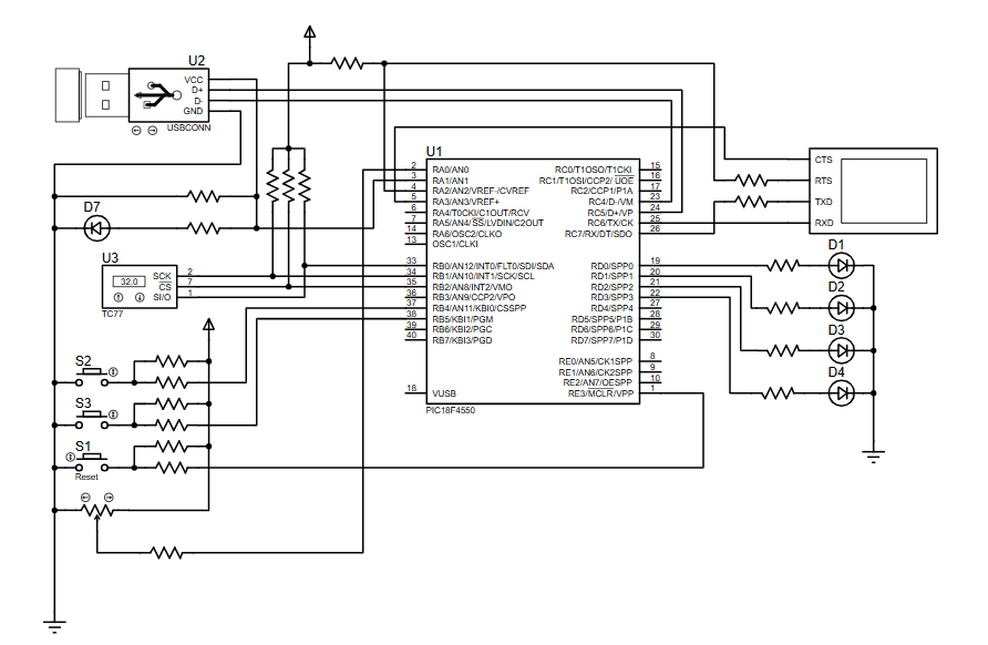
Proteus Simulation
The Proteus simulation of this project accurately replicates USB CDC communication behavior. When the simulation runs:
- The USB module connects to a virtual PC environment
- The virtual terminal displays transmitted/received data
- LEDs respond to input changes
- Switch presses trigger real-time responses
This makes it easy to test embedded systems firmware without needing physical hardware.
Conclusion
The PICDEM FS USB CDC Evaluation Board using PIC18F4550 with Proteus simulation is an excellent embedded systems project for understanding USB communication. It demonstrates how microcontrollers can interact with PCs using virtual serial ports, making it highly relevant for modern DIY electronics and firmware development.
Whether you’re learning USB protocols or building real-world applications, this project provides a solid foundation in microcontroller-based USB interfacing
Complete File
PICDEM FS USB CDC Evaluation Board using PIC18F4550 with Proteus Simulation
Quick Solutions to Questions related to PICDEM FS USB CDC Evaluation Board:
- How does the project enable communication with a PC?
The PIC18F4550 uses its built-in USB module to establish CDC protocol communication, behaving like a virtual serial port. - Can this project be tested without physical hardware?
Yes, the system is fully testable using Proteus simulation to replicate USB CDC behavior. - What components provide user input to the system?
Three push buttons labeled S1, S2, and S3 are used for user interaction and control signals. - How does the system display status information?
Five LEDs designated as D1 through D4 and D7 visualize system status or received/transmitted data. - Does the microcontroller require external clock components?
No, the design includes a Clock Module (TC77) to ensure proper timing for MCU operations. - What role does the Virtual Terminal play in the workflow?
The Virtual Terminal simulates UART communication for debugging and monitoring serial data transmission. - Is there a reset function included in the design?
Yes, the project features reset functionality for system control. - What specific protocol is utilized for USB communication?
The project uses the Communication Device Class (CDC) protocol for data exchange.
Related projects
PICDEM FS USB Mass Storage Device using PIC18F4550 with Proteus Simulation
Introduction This microcontroller project demonstrates how to simulate a USB Mass Storage Device (MSD) using the PIC18F4550 in a Proteus simulation environment....
Development Boards & Kits · PIC18F2550Pinguino Project: A PIC Microcontroller Based Arduino
This is a complete tutorial to make a PIC Microcontroller based Arduino. This is a complete tutorial to make PIC microcontroller based...
Beginner Tutorials · PIC18F4550How to work with inbuilt ADC Module of PIC18F4550
A microcontroller, a digital device, can read, execute and transmit only digital signals. On the contrary, the outputs of the most of...
Beginner Tutorials · PIC16F877APIC16F877 Driving LCD in 4-Bit Mode using PIC16F877 with Proteus Simulation
Introduction This microcontroller project shows how a PIC16F877 can drive an LCD display using 4-bit mode inside a Proteus simulation.The project demonstrates...
Beginner TutorialsPIC12CE518 I2C EEPROM using PIC12CE518 with Proteus Simulation
Introduction This microcontroller project demonstrates how to write and read data using the internal I2C EEPROM of the PIC12CE518 and visualize the...
Beginner TutorialsPico Timer Project using Pico with Proteus Simulation
Introduction Timers are one of the most important features in embedded systems because they allow microcontrollers to perform tasks at precise intervals...

Ibrar Ayyub
I am an experienced technical writer holding a Master's degree in computer science from BZU Multan, Pakistan University. With a background spanning various industries, particularly in home automation and engineering, I have honed my skills in crafting clear and concise content. Proficient in leveraging infographics and diagrams, I strive to simplify complex concepts for readers. My strength lies in thorough...