
Summary of PIC16F627 RPM MEASUREMENT CPU FAN SPEED INDICATOR CIRCUIT
This project is a PIC16F627-based RPM measurement circuit that measures CPU/fan speed independently of the PC and displays the result on four 7-segment displays. The firmware is written in PIC assembly. It can also show fan speed via PC software or be checked in BIOS when installed in a system. The device is intended as a standalone CPU cooler/fan speed tester.
Parts used in the PIC16F627 RPM MEASUREMENT CPU FAN SPEED INDICATOR CIRCUIT:
- PIC16F627 microcontroller
- 4 units of 7-segment displays
- Resistors (for segment current limiting and pull-ups)
- Transistors or driver ICs (to drive 7-segment displays)
- Crystal or resonator (clock source for PIC)
- Capacitors (decoupling and for oscillator)
- Connector for fan tachometer input
- Power supply components (regulator, capacitors)
- PC interface components (optional, for Windows application connection)
- PCB or prototyping board and wiring
PIC16F627 Measures CPU Fan Speed Independently
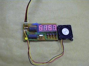
This project uses a PIC16F627 microcontroller to measure the rotational speed of a CPU cooling fan without requiring a computer or BIOS monitoring software. The fan’s tachometer output provides pulses that the microcontroller can count and convert into revolutions per minute, while four 7-segment displays show the calculated speed
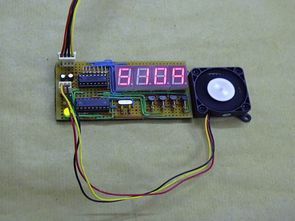
A standalone tester can be useful when checking cooling fans away from their normal motherboard or when comparing fan operation during electronics testing and repair.
Fan Tachometer Pulses Provide Speed Information
Many brushless DC computer fans include a tachometer output that generates electrical pulses as the rotor turns. The PIC16F627 monitors these pulses and uses their frequency to determine how quickly the fan is rotating.
The tachometer output on many fans is open-collector, so a pull-up resistor is required to produce a valid logic-high voltage when the output transistor is inactive. This gives the microcontroller a clear digital waveform that can be counted reliably.
Pulses Per Revolution Must Be Included in RPM Calculations
Simply multiplying measured frequency by 60 only produces the correct RPM when the fan generates exactly one tachometer pulse per revolution. Many PC cooling fans generate two pulses for each complete rotation.
The more general calculation is: RPM = (Pulse Frequency × 60) ÷ Pulses Per Revolution
For example, a 60Hz tachometer signal from a fan producing two pulses per revolution represents 1,800 RPM rather than 3,600 RPM. Knowing the fan’s pulses-per-revolution specification is therefore essential for accurate measurement.
PIC Timers Create the Measurement Interval
The project uses the PIC16F627’s TMR0 and TMR1 timer resources to count tachometer activity and determine elapsed time. One approach is to count the number of incoming pulses during a fixed interval such as one second and then convert that result into RPM.
Another method is to measure the time between successive tachometer pulses. Period measurement can be particularly useful at lower rotational speeds because the controller does not need to wait for a large number of pulses before calculating a result.
Four-Digit Display Shows Fan RPM
Four 7-segment displays provide a straightforward numerical output for measured fan speed. A reading such as 5109 RPM can therefore be displayed directly without requiring a computer, serial terminal, or graphical screen.
Using four digits is appropriate for many small cooling fans because their normal rotational speeds commonly fall within a range that can be represented using four decimal digits.
Multiplexing Reduces Display Wiring
Driving four complete 7-segment displays independently would require many microcontroller connections. This project instead uses multiplexing, where only one digit is actively driven at a particular moment.
The PIC rapidly switches between the four displays while changing the segment pattern for each digit. When this process occurs sufficiently quickly, persistence of vision makes the viewer perceive all four numbers as continuously illuminated.
The original example uses approximately 20ms per digit. Display-refresh timing should be chosen carefully because excessively slow multiplexing can produce visible flicker, while unnecessarily long on-times can reduce the smoothness of the display.
CD4511 Reduces Microcontroller Pin Requirements
A CD4511 BCD-to-7-segment decoder is used between the PIC16F627 and the displays. Instead of having the microcontroller directly generate all seven segment signals, it provides a four-bit BCD value representing the required decimal digit.
The CD4511 converts that value into the correct segment pattern. This reduces the number of microcontroller pins dedicated to display control and simplifies the firmware needed to show decimal numbers.
Transistors Select Individual Display Digits
Separate transistors switch the individual 7-segment displays during multiplexing. The microcontroller can therefore select which digit is active while the CD4511 determines which number appears on that digit.
If the switching transistors become noticeably warm, their current, power dissipation, base drive, and selected device ratings should be checked. Adding a heat sink may reduce temperature, but excessive heating can also indicate that the circuit should be reviewed rather than assuming additional cooling is the only solution.
Stable Power Helps Maintain Accurate Measurements
Display multiplexing produces rapidly changing current loads that can introduce electrical noise into the circuit. Because the same microcontroller is also measuring timing-sensitive tachometer pulses, good power-supply design is important.
A stable regulated supply and suitable decoupling capacitor close to the PIC16F627 can help prevent voltage disturbances from interfering with pulse detection or processor operation. Careful grounding and signal routing can provide additional reliability when the circuit is transferred from a prototype to a PCB.
Optical Feedback Demonstrates Another RPM Method
The additional motor-speed project uses an optocoupler and rotating disc rather than a fan’s built-in tachometer output. Two openings in the disc interrupt the optical path as the motor rotates, producing two pulses for every revolution.
Because the number of openings is known, the controller can calculate speed from the measured timing of the resulting signal. This demonstrates the same fundamental principle as the CPU fan tester: rotational motion is converted into electrical pulses, and the relationship between those pulses and one complete revolution is used to determine RPM.
RPM Measurement Is a Useful Microcontroller Project
This circuit combines several important embedded-system concepts in one practical application: digital pulse measurement, hardware timers, frequency-to-RPM conversion, display multiplexing, BCD decoding, transistor switching, and signal conditioning.
Understanding these techniques provides a useful foundation for other speed-measurement projects involving motors, fans, wheels, shafts, optical encoders, Hall-effect sensors, and other rotating equipment.
Source: PIC16F627 RPM MEASUREMENT CPU FAN SPEED INDICATOR CIRCUIT
- What microcontroller is used in this rpm measurement circuit?
The circuit uses a PIC16F627 microcontroller. - How is the fan speed displayed?
The speed is displayed on four 7-segment displays. - Is the tester independent of the computer?
Yes, it measures and displays fan speed independently of the computer. - Can the fan speed be read in Windows?
Yes, the project mentions displaying the speed on an application in Windows. - Can the fan speed be read in BIOS?
Yes, you can also read the fan speed in the BIOS menu when the computer resets. - What language is the firmware written in?
The software/firmware is written in PIC assembly language. - What is the project intended to test?
It is intended to measure and test CPU cooler and case fan speeds. - How many 7-segment displays are used?
Four 7-segment displays are used to show the RPM.
