


Summary of Serial to PIC Interface using PIC Microcontroller
This article describes a single-pin serial interface circuit connecting a computer terminal to a PIC microcontroller. It enables bidirectional communication by converting TTL logic to RS-232 levels using DTR or RTS signals for control. The setup prevents data echo and simplifies debugging by allowing input and output through one pin.Parts used in the Serial to PIC Interface:
- PIC Microcontroller
- Terminal program (computer)
- DTR signal (pin 4)
- RTS signal (pin 7)
- CTS/RTS hardware handshaking
- TTL true data line
- RS-232 level converter
What about projects that do not have I/O? This device sneeks both input and output from your computer (terminal program) to the PIC using just one pin.
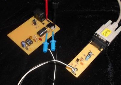
In order for this circuit to work, you need to set either DTR (pin 4) or RTS (pin 7) to positive voltage. Turning on CTS/RTS hardware handshaking usually does this.
All serial data from the computer is transfered to the PIC as TTL true data. TTL true data from the PIC is converted to rs-232 level and sent back to the computer. Additionally, the transmitted data from the computer is prevented from echoing directly back (CR4 above).
Here is some SAMPLE CODE at the PIC end that sends and receives on a single pin allong with the LAYOUT and PARTS PLACEMENT.
For more detail: Serial to PIC Interface using PIC Microcontroller
Quick Solutions to Questions related to Serial to PIC Interface:
- How does this device handle input and output?
The device sneaks both input and output from your computer to the PIC using just one pin. - What voltage is required for the circuit to work?
You need to set either DTR (pin 4) or RTS (pin 7) to positive voltage. - Does turning on CTS/RTS hardware handshaking affect the circuit?
Yes, turning on CTS/RTS hardware handshaking usually sets the necessary pins to positive voltage. - How is serial data transferred from the computer to the PIC?
All serial data from the computer is transferred to the PIC as TTL true data. - How is data sent back to the computer?
TTL true data from the PIC is converted to rs-232 level and sent back to the computer. - Is there a risk of data echoing directly back?
No, the transmitted data from the computer is prevented from echoing directly back. - Can you send and receive on a single pin with this setup?
Yes, the sample code sends and receives on a single pin along with the layout and parts placement. - Why is this method useful for debugging?
It helps in debugging the code as you write it by getting I/O working early.
Related projects
CAN FD Node based on a PIC18 Microcontroller
The introduction sets the stage for an embedded systems project that involves developing a Embedded C CAN FD project using the MCP2517FD...
Communication & InterfacingLAN9662 Gigabit Switch: Optimized for Industrial Ethernet
Introduction It should come as little surprise therefore that one element of what is now more commonly referred to in some circles...
Communication & InterfacingPIC Microcontroller: Fundamentals & Applications for Students
Introduction Microcontrollers are the key components in the embedded systems market. A variety of embedded systems was formed and developed after the...
Communication & Interfacing10BASE-T1S Ethernet: Simplified OEM Design for Auto Devices
Introduction Cars these days are surrounded by technology. They come loaded with all sorts of electronic gadgets and sensors. This project wants...
Communication & InterfacingDesigning a Microcontroller Framework for PC-Based Control of Electrical Appliances
ABSTRACT The preference for personal computers as a platform for designing and implementing control algorithms is growing due to the ease of...
Communication & InterfacingEfficient Multichannel Data Acquisition with USB Connectivity using PIC Microcontroller
1. INTRODUCTION With the rapid advancements in embedded technology, there is a growing demand for a data acquisition system that combines fast...

Ibrar Ayyub
I am an experienced technical writer holding a Master's degree in computer science from BZU Multan, Pakistan University. With a background spanning various industries, particularly in home automation and engineering, I have honed my skills in crafting clear and concise content. Proficient in leveraging infographics and diagrams, I strive to simplify complex concepts for readers. My strength lies in thorough...