


Summary of Ultrasonic Obstacle-avoiding Robot
RekaBot is a DIY obstacle-avoiding robot that uses an ultrasonic sensor and servo motor to detect walls and navigate around them by driving toward the widest path. The project involves designing custom PCBs, assembling a Zumo chassis with gearmotors, programming a PIC18F4550 microcontroller, and debugging power systems using specialized tools like an oscilloscope and PicKit programmer.Parts used in RekaBot:
- Zumo Robot chassis
- Pololu micro gearmotors 1:100
- HCSR04 ultrasonic sensor
- SG90 servo motor
- DRV8801 carrier boards
- MC34063 DC-DC converter IC
- PIC18F4550 microcontroller
- USB socket
- DIP40 and DIP8 IC holders
- Lithium-Ion batteries
- Inductors, capacitors, resistors, diodes, transistors, LEDs
- PCBs and ferric chloride
- Soldering iron, solder, flux, solder wick
- PicKit2 and PicKit3 programmers
- Multimeters
- Serial to USB converter
This is my attempt at designing and building an obstacle avoiding robot! RekaBot (named after a fairy (: ) can detect obstacles with an ultrasonic sensor that can move around with help from a servo. Based on the measurements she takes, the tracks are driven towards the direction with the biggest distance - avoiding obstacles.
Read in and try to build one yourself!
Step 1: Concept, Drawings and Preliminary BOM
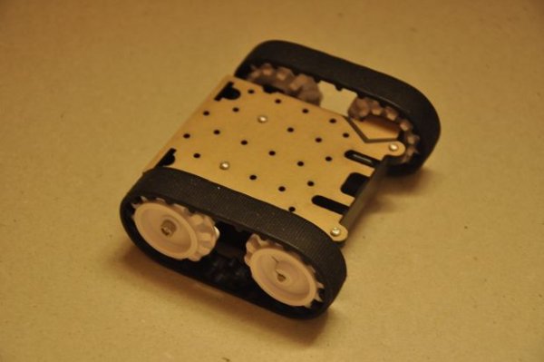
In this project I will tell the story of how RekaBot was built. The target is to build a robot which is capable of avoiding walls and obstacles in an infinite loop.
What do we need in order to build this bot:
- Zumo Robot chassis - ebay
- Pololu micro gearmotors 1:100 - ebay
- HCSR04 ultrasonic sensor - ebay
- SG90 servo motor - ebay
- DRV8801 carrier boards - pololu
- MC34063 DC-DC converter IC - ebay
- PIC18F4550 microcontroller - ebay
- USB socket - ebay
- DIP40, DIP8 IC holders - ebay, ebay
- Lithium-Ion batteries - ebay
- inductors, capacitors, resistors - local electronics shop
- diodes, transistors, LEDs - local electronics shop
- PCBs, ferric chloride, laser printer, acetone
- drills, bits, saw, screwdriver, hammer, pliers, tweezers, sand paper
- soldering iron, solder wik, solder, flux
- PicKit2, PicKit3, for programming
- multimeters for voltage and current measurements
- a laptop with useful software on it, printer
- serial to USB converter - ebay
What I had extra:
- heat gun to salvage components from old boards
- third hand for soldering components
- power supply for tests
- digital storage oscilloscope
- lots of components in stock for quick tests
Long story short
I started with ordering components off E-Bay and local sites, starting with the robot chassis. Nothing special here, just the fact that they shipped without the motors, this hurt a bit - I wasn't expecting that. I found the warning on their website eventually: "no motors included!". Of course, it had a link to a quite expensive motor, so I ended up purchasing them separately. After I got those, I assembled the chassis, and drew some initial schematics. With the schematics done, I designed the PCBs with AD14, made the artwork prints on shiny paper, etched and drilled some PCB's, and soldered the components. Looking back, I can say that all the stuff mentioned in the two lists were really helpful, the oscilloscope in particular. It was extremely useful for debugging the PSU board, all four converters were in trouble at first power-up, but thanks to my RIGOL DZ1104, the errors were easy to locate, and I eventually succeeded powering everything up.
After I got rid of the obvious hardware problems, I used a PicKit3 to write a bootloader into the PIC. This is an important step to fast program update, not to mention, that it only needs a free USB port from the laptop, there's no need to take your programmer everywhere. Once that was done, I ended up calculating timers, setting up time bases, and writing the C routines for the servo motor, ultrasonic range sensor, LEDs, and other stuff that needed to be handled.
When I got to a point where I was able to turn the servo at any given angle, and read an approximate distance to the closest obstacle with the HC-SR04, I developed a super-simple algorithm which leads the robot away from the obstacles. Once the testing was done, I gathered all the photos I took, all the memo-s I wrote to myself, and compiled it into this instructable for you to read and re-make. I hope you'll find it interesting, and will try to make one yourself!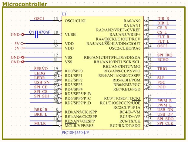
For more detail: Ultrasonic Obstacle-avoiding Robot
-
What is the main function of RekaBot?
It detects obstacles with an ultrasonic sensor and moves tracks toward the direction with the biggest distance to avoid them. -
How does the robot determine which direction to move?
The robot drives towards the direction with the biggest distance based on measurements taken by the ultrasonic sensor. -
Which microcontroller is used in this project?
A PIC18F4550 microcontroller is used to handle the routines for the servo motor, ultrasonic range sensor, and LEDs. -
What tool was crucial for debugging the power supply unit?
An RIGOL DZ1104 digital storage oscilloscope was extremely useful for locating errors in the PSU board converters. -
How are updates made to the robot's software?
A bootloader written via PicKit3 allows for fast program updates using only a free USB port from a laptop. -
Why were the motors purchased separately from the chassis?
The Zumo Robot chassis shipped without motors because the seller had a link to expensive motors included instead. -
What software was used to design the PCBs?
AD14 was used to design the PCBs after drawing initial schematics.
Related projects
PICDEM FS USB CDC Evaluation Board using PIC18F4550 with Proteus Simulation
Introduction The PICDEM FS USB CDC Evaluation Board is a practical microcontroller project built around the PIC18F4550, designed to demonstrate USB communication...
Peripheral Tutorials · PIC18F4550PICDEM FS USB Mass Storage Device using PIC18F4550 with Proteus Simulation
Introduction This microcontroller project demonstrates how to simulate a USB Mass Storage Device (MSD) using the PIC18F4550 in a Proteus simulation environment....
Development Boards & Kits · PIC18F2550Pinguino Project: A PIC Microcontroller Based Arduino
This is a complete tutorial to make a PIC Microcontroller based Arduino. This is a complete tutorial to make PIC microcontroller based...
Motors & RoboticsReal-Time CAN-Based Vehicle Monitoring System with PIC MCU
INTRODUCTION The Controller Area Network (CAN) is a robust vehicle communication bus standard that was primarily developed for automobile applications but has...
Motors & RoboticsEasy Way to Learn Robotics Using Microcontrollers: A Beginner’s Guide
The title, "Easy Way to Learn Robotics Using Microcontrollers," promises an accessible entry point for those curious about the exciting world of...
Motors & Robotics · PIC16F877AEfficient Sun-Following Robot: A Solar Tracker with Microcontroller Control
Abstract The impending global challenge of dwindling non-renewable fuel resources underscores the urgency of transitioning towards renewable energy alternatives like solar power....

Ibrar Ayyub
I am an experienced technical writer holding a Master's degree in computer science from BZU Multan, Pakistan University. With a background spanning various industries, particularly in home automation and engineering, I have honed my skills in crafting clear and concise content. Proficient in leveraging infographics and diagrams, I strive to simplify complex concepts for readers. My strength lies in thorough...