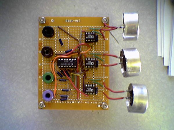
The ultrasonic position system uses ultrasonic transmitters/receivers to triangulate position of the robots used in GE423. Each of three transmitters uses a distinct frequencies: 23 kHz, 31 kHz, and 40 kHz. The 2812 DSP is used to measure signal timing and calculate position based on these values. The design of the electronics, as well as discussion of the software development is presented below.
The electronics were not intergrated with the 6713 DSP on the robot.
Note: To get around the issue of clock syncing, the robot will start in a known position, and calculate position for four cycles before proceeding. An alternative to this would be to add a fourth transmit frequency and use the 4th signal to sync the robot clock with the transmit clock.
1.0 Hardware
A wide variety of hardware was used for this project. The hardware was chosen based on availability and price. By no means is the solution presented “the best”or the only way to achieve the desired results, but it is a workable solution.
1.1 Ultrasonic Transmitters/Receivers
The ultrasonic sensor were purchased from Massa. The TR-89/B series where chosen because they come in 3 different frequencies, and they were stock parts. There is no pdf data sheet available on the Massa website, all information if available here. The main drawback of using Massa is there $500 minimum order, and the sensors aren’t cheap at about ~$30 each.
Details on the components of the transmit circuit can be found in the subsection below:
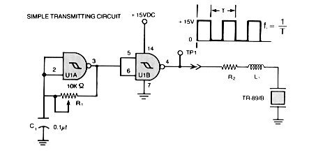
1.2.1 Frequency Generation
The transmit circuit take from the Massa Website looks like:
Source:http://www.massa.com/datasheets/graphics/tr89_data.gif
Where R1 is a 10k 10 turn precision wound potentiometer, and U1 is a CD4039B NAND Schmitt Trigger. The tuning resistor R2 and L where left out to increase the transmit power around the base frequency. The potentiometer was adjusted until the frequency was the desired base frequency. A 1k resistor was added in parallel with the potentiometer to give a higher resolution. For the 40 kHz case, a smaller capacitor was required to reach the base frequency. Make sure to tune the circuit with the ultrasonic transducers attached, because the additional impedance will change the transmit frequency. The 12 Vdc was generated by a lab supply.
The output at point TP1, is a 12V peak to peak is a square wave at the desired frequency. The point TP1 was connected to the Driver Signal Circuit presented below.
1.2.2 555 Timer Circuit
The documentation for the 555 timer can be found here. An a picture of how it is wired can be
seen below:
Source:http://www.williamson-labs.com/480_555.htm
Using the handy calculator for Ra, Rb, and C found here, Ra=100k ohm, Rb=200k ohm, and C=2.2 mircoF.
1.2.3 Driver Signal Circuit
The 35 Vdc supply is manufactured by Ultravolt, part number 1/4Aa24-P30. This supply is actually a 0-250 Vdc supply that uses a potentiometer to control voltage output.
About The Author
Ibrar Ayyub
I am an experienced technical writer holding a Master's degree in computer science from BZU Multan, Pakistan University. With a background spanning various industries, particularly in home automation and engineering, I have honed my skills in crafting clear and concise content. Proficient in leveraging infographics and diagrams, I strive to simplify complex concepts for readers. My strength lies in thorough research and presenting information in a structured and logical format.
Follow Us:LinkedinTwitter