


Summary of Project Board using PIC18F2550 microcontroller
This article describes a PIC18F2550 development board designed for student microcontroller projects, specifically instrumentation. It features an MCU with optional internal oscillator, dual ADCs (sigma-delta and 10-bit), LCD connectors, USB connectivity, and onboard power regulation. The board supports easy code programming via an ICSP header and allows students to build signal conditioning modules that plug directly into the platform.Parts used in the PIC18F2550 Project Board:
- PIC18F2550 Microcontroller
- External Crystal Oscillator (optional)
- LTC2400 or LTC2420 Sigma-Delta Converter
- 10-bit ADC (6-channel)
- Text LCD Connector (JR1)
- GLCD Connector (JF1)
- Type B USB Connector
- Low Dropout Regulator
- Rechargeable Battery (BT1)
- 10-pin ICSP Header (J1)
- LM336 Voltage Reference
- Jumper for Noise Rejection (J3)
- Debug LED (D2/U2 context)
The board features
MCU: PIC18F2550 with external xtal,
ADC: one channel 0-2.5V sigma-delta converter, Linear Technology LTC2400/LTC2420,
6-channal 10-bit ADC 0-5V,
Display: Two connectors for text LCD or GLCD,
USB: onchip USB port with type B connector,
Power supply: onboard low dropout regulator, rechargeable battery,
Code programming: 10-pin header for In Circuit Loader.
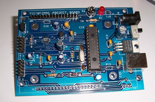
The board platform is suitable for developing the microcontroller based instrumentation. Students may build the signal conditioning board, plugs it to PIC project board, develops the code and programs it with loader cable easily.
Hardware
The MCU is 28-pin PIC18F2550 with external xtal as the option. We can use internal oscillator. The loader uses only three pins, PGD, PGC and MCLR. J1 is ICSP header, we can plug it to the application board for both code loading and running. The user I/O ports is 6-channel analog input RA0-RA5. PORTB, RB0-RB7 is for LCD interface. User can choose either text LCD at JR1 connector or GLCD at JF1 connector. PORTC, RC0-RC2 is used to interface the LTC2400/LTC2420 SPI bus, sigma delta converter. RC4 and RC5 is USB port signal. RC6 is also available at J2. RC7 is debug LED. J1 is ICSP header. D2 protects VCC from high voltage programming at MCLR pin. U2 can be 20-bit or 24-bit resolution, sigma-delta converter, LTC2420 or LTC2400. J3 is jumper for selecting rejection of the common mode noise frequency, 50Hz or 60Hz. The reference voltage, +2.5V is generated by U3 LM336. The board can be powered by rechargeable battery, BT1.
For more detail: Project Board using PIC18F2550 microcontroller
-
What is the main purpose of this project board?
The board serves as a development platform for student projects and microcontroller-based instrumentation. -
Which microcontroller is used on the board?
The board uses a 28-pin PIC18F2550 microcontroller. -
Can the board use an internal oscillator instead of an external one?
Yes, the internal oscillator can be used as an option alongside the external crystal. -
How many analog input channels are available for user I/O?
There are 6-channel analog inputs available on ports RA0 through RA5. -
What types of displays can be connected to the board?
The board has connectors for both text LCDs at JR1 and GLCDs at JF1. -
How is the code loaded onto the microcontroller?
Code is loaded using a 10-pin ICSP header (J1) connected to an In Circuit Loader. -
What components are used for the sigma-delta converter?
The board utilizes either the LTC2400 or LTC2420 for the 20-bit or 24-bit resolution conversion. -
How is the reference voltage generated?
A +2.5V reference voltage is generated by component U3, which is an LM336. -
What is the function of jumper J3?
Jumper J3 selects the rejection of common mode noise frequency, allowing a choice between 50Hz or 60Hz. -
How is the board powered?
The board can be powered by an onboard rechargeable battery (BT1) or an onboard low dropout regulator.
Related projects
Pinguino Project: A PIC Microcontroller Based Arduino
This is a complete tutorial to make a PIC Microcontroller based Arduino. This is a complete tutorial to make PIC microcontroller based...
Audio, Sound & Radio · PIC18F2550LM386 based stereo audio amplifier with digital volume control using PIC18F2550
Due to its simplicity (requires minimum external components) and high availability, LM386 is very popular among hobbyists for use in low-voltage audio...
Meters & Test Instruments · PIC18F2550Harmonic Distortion Meter using PIC18F2550
The 3rd harmonic distortion meter has been designed for measuring the quality of AC supply. The meter is built with a PIC18F2550...
Development Boards & Kits · PIC18F4520Voltage Measurement with A PIC Microcontroller
Voltage Measurement with PIC Microcontroller articulates a methodical framework for facilitating analog voltage measurement using the PIC18F4520, an advanced member of Microchip’s...
Development Boards & KitsUltra-Low Power: Microcontroller Standby Current to 130uA with OPEnS Power Control Board
At the OPEnS Lab, a key focus for our projects is achieving exceptionally long battery life. This was particularly true for the...
Development Boards & KitsAn Integrated Approach to Developing Applications with Microchip PIC Microcontrollers
1. Introduction In our daily lives, a variety of devices such as telephones, household appliances, and cars incorporate "smart" electronics, typically manifested...

Ibrar Ayyub
I am an experienced technical writer holding a Master's degree in computer science from BZU Multan, Pakistan University. With a background spanning various industries, particularly in home automation and engineering, I have honed my skills in crafting clear and concise content. Proficient in leveraging infographics and diagrams, I strive to simplify complex concepts for readers. My strength lies in thorough...