
Summary of PIC16F877 AIR RGB WRITING
The article details a DIY "Air RGB Writing" project using the PIC16F877 microcontroller. The author describes building a circuit with a motor and mechanical system to create light patterns in the air. Although the initial prototype faced challenges with mechanical stability and power supply, the author plans to refine the design using SMD components like transistors, resistors, and LEDs for better performance.
Parts used in the PIC16F877 Air RGB Writing:
- PIC16F877 microcontroller
- Motor
- Motor shaft
- Mobile phone battery connector
- 1000mf 10v capacitor
- Transistors (planned for next version)
- Resistors (planned for next version)
- SMD LEDs (planned for next version)
PIC16F877 RGB Persistence-of-Vision Display Project
The PIC16F877 RGB Persistence-of-Vision Display is an electronics project designed to create the visual effect of text appearing to float in mid-air. It uses a rapidly rotating row of RGB LEDs controlled by a PIC16F877 microcontroller, with the LEDs switching at carefully timed intervals as the circuit rotates.
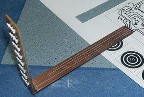
This type of display relies on persistence of vision, where rapidly changing points of light can appear to the human eye as a complete image or line of text when their movement and timing are correctly synchronized.
How the RGB Persistence-of-Vision Effect Works
Instead of using a fixed matrix of LEDs, a persistence-of-vision display moves a much smaller number of LEDs through space.
As the PCB rotates, the PIC16F877 changes the RGB LED pattern at specific positions. When this happens quickly enough, the viewer perceives the individual light pulses as complete letters, shapes or patterns rather than separate LEDs moving in a circle.
Accurate timing is therefore just as important as the electronic circuit itself. Incorrect timing or unstable motor speed can cause characters to appear distorted, stretched or unstable.
Using the PIC16F877 for LED Control
The PIC16F877 acts as the main controller for the display. Its program determines when individual RGB LED channels turn on and off as the board rotates.
For a working POV display, the microcontroller must coordinate LED data with the rotational position of the PCB. The original project included the required software and code so that other electronics enthusiasts could study the design and further develop it.
Supplying Power to a Rotating PCB
One of the difficult parts of a rotating electronic display is supplying continuous electrical power without fixed wires restricting movement.
In this project, circular PCB contact rings were mounted around the motor shaft. A spring-loaded mobile-phone battery connector was then used to make electrical contact with the rings while the circuit rotated.
Spring contacts are useful in this type of arrangement because they can maintain pressure against a moving conductive surface while allowing continuous rotation.
However, the rings need to remain smooth, clean and concentric. Irregular surfaces or poor contact can interrupt the supply voltage and cause the PIC16F877 to reset.
Stabilizing the Microcontroller Power Supply
A large input capacitor was included to help maintain the circuit voltage during very short interruptions between the rotating contacts.
This can reduce the likelihood of a microcontroller reset caused by momentary power loss, but it should not be considered a substitute for reliable mechanical contact.
Local decoupling close to the PIC16F877 power pins is also important for suppressing short voltage disturbances produced by switching loads and imperfect contacts.
Before operating the system at normal speed, the contact resistance and power stability should first be checked while the assembly rotates slowly.
Mechanical Balance Is Critical
The initial design encountered significant vibration because the rotating PCB was relatively large.
Mechanical balance is especially important in a PIC16F877 RGB Persistence-of-Vision Display because even a small uneven distribution of mass can produce substantial vibration as rotational speed increases.
Heavier components should generally be located closer to the motor shaft where possible, while the LED arrangement must still remain at the required radius for producing the display.
The PCB, fasteners, connectors and other rotating parts also need to be securely attached.
Why an SMD Version Can Improve the Design
Rebuilding the circuit with SMD components can make the rotating assembly smaller and lighter.
Surface-mount LEDs, resistors, transistors and other components require less PCB space than many through-hole alternatives. Reducing the overall mass can make balancing easier and may reduce the mechanical forces generated during rotation.
A more compact layout can therefore be useful when developing a future version of the display.
Synchronizing the Display with Rotation
A reliable POV display needs a known reference position for every revolution.
An optical or magnetic sensor can be used to generate a reference pulse when the rotating PCB reaches a specific position. The PIC16F877 can then use this signal to start displaying each character or image from the same angular point.
Without a reference position, small changes in motor speed may cause the displayed text to move around the rotation path or become visually unstable.
Adjusting Display Timing
The rotational speed and timing values inside the microcontroller program need to work together.
If the displayed text appears stretched, compressed or misaligned, both factors should be checked rather than adjusting only the LED data.
A faster rotation changes how much angular distance the LEDs travel during each programmed delay, so timing values that work at one motor speed may not produce the same visual result at another.
RGB LED Current and Driver Requirements
Each RGB LED contains separate color channels, and each channel requires appropriate current control.
Current-limiting resistors should therefore be selected according to the LED and circuit requirements. Where driver transistors are used, they must also be capable of handling the combined pulsed current drawn by the active LED channels.
This becomes increasingly important when several LEDs or color channels are switched simultaneously.
Safety When Testing a Rotating POV Display
A rapidly rotating PCB presents a mechanical hazard in addition to the normal electrical considerations of an electronics project.
All components, mounting screws and connectors must be securely fixed before high-speed testing. Initial operation should be carried out at reduced motor speed so that vibration, balance and electrical contact can be checked safely.
Using a protective cover or enclosure during testing provides additional protection if a component or mounting part becomes loose.
Project Limitations and Development Status
The original RGB POV circuit and software were developed, but the complete mechanical system was not finalized.
The project was connected to a motor during testing, where the size of the PCB caused severe vibration. This highlighted one of the most important lessons of rotating-display design: successful electronics and software alone are not enough if the mechanical assembly cannot remain stable.
A redesigned SMD-based PCB, improved balancing and a dependable rotational reference system would all be important considerations for developing the concept further.
Final Overview
The PIC16F877 RGB Persistence-of-Vision Display demonstrates how microcontroller programming, RGB LED control and mechanical rotation can be combined to create text that appears suspended in space.
Its most challenging areas are not limited to programming. Stable rotating power contacts, precise synchronization, balanced PCB construction, suitable LED drivers and safe mechanical mounting all contribute to the quality and reliability of the final display.
For electronics enthusiasts studying microcontrollers, LED control and electromechanical design, the project also provides a practical example of how software, electronics and mechanical engineering need to work together in a single system.
Source: PIC16F877 AIR RGB WRITINGIsis proteus simulation of air writing applications ares pcb and code files: pic16f877-air-rgb-writing.ZIP
- What is the main purpose of this project?
The project creates an air writing application that displays RGB light patterns. - Which microcontroller is used in the circuit?
The PIC16F877 microcontroller is used to control the application. - How is the power supplied to the circuit?
The circuit runs using a mobile phone battery connected via a mobile phone battery connector. - What component ensures a fixed input voltage?
A 1000mf 10v capacitor is used at the input voltage to ensure it remains fixed. - Did the initial mechanical system work perfectly?
No, the mechanical system could not keep up and had issues with interruption. - Why did the author need to run the system in a window initially?
The mechanism design required running in a specific area due to enthusiasm and setup constraints. - What changes are planned for the next version?
The author plans to include transistors, resistors, and SMD LEDs in the new circuit. - Where can I find the simulation and code files?
The files including Isis Proteus simulation, Ares PCB, and code are available as pic16f877-air-rgb-writing.ZIP.
