
Summary of Two-Channel PC Based Oscilloscope USB
This article describes a compact, two-channel PC-based oscilloscope using a PIC18F2550 microcontroller and USB connectivity. It eliminates the need for an external power supply by utilizing the PC's USB port, offering ±16V input range and up to 10 kHz operation. The design features programmable gain amplifiers (MCP6S91) and voltage-shifting op-amps (LF353) to handle bipolar signals, controlled via SPI. Software written in C handles calibration and data acquisition, with specific driver installation instructions provided for Windows systems.
Parts used in the Two-Channel PC Based Oscilloscope:
- PIC18F2550 microcontroller
- MCP6S91 programmable gain amplifier
- LF353 operational amplifier
- ICL7660 DC-DC voltage converter
- PIC18F2445 microcontroller (alternative)
- MAX1044 voltage converter (alternative)
- 4.7-kiloohm presets
- USB cable
Inroduction
More and more experiments are now ‘PC-assisted.’ Also conventional acquisition systems are very expensive. Since portable PCs are today common and a USB link is a better solutionhere we present an oscilloscope using USB port of the PC that operates at up to 10 kHz with ±16V input voltage. It has much more improved features than the PC-based oscilloscope . The oscilloscope uses IC PIC18F2550 from Microchip as the main controller, which makes the oscilloscope compact as there is no need of additional power supply for the entire circuit board.
Circuit description
At the heart of this oscilloscope is USB2.0-compliant microcontroller PIC18F2550 from Microchip. You can also use IC18F2445 in place of PIC18F2550. Specifications of this microcontroller are:-
Features of 18F2550
Programming
- Up to 32 kB of flash memory, 2kB RAM and 256-byte EEPROM
- Extended instruction set (optimised for ‘C’ compiler)
- 8×8 single-cycle multiplier
- Single-supply serial programming and easy debugging
USB transceiver
- USB1.1 and 2.0 from 1.5 MB/s to 12 MB/s
- Isochronous, bulk and interrupt transfer modes
- 1 kB of access RAM usable with 32 endpoints (64 bytes each)
Multiple oscillator and power modes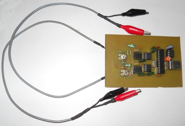
- From internal 31 kHz to external 48 MHz with PLL
- Possible software switching between ‘run,’ ‘idle’ and sleep
modes. In sleep mode, current is down to 0.1 μA.
- Wide operating voltage range (2.0V to 5.5V). Useful for battery
operations.
Complete set of classical peripherals
- Several input/output (I/O) ports, four timers with capture/
compares
- Synchronous and asynchronous enhanced modules
- Streaming parallel port
- 10-bit ADC module with up to 13-channel multiplexer.
This microcontroller has a USB2.0-compliant transceiver and a CPU running up to 12 MIPS.
avobe figrue shows the circuit of the two-channel PC-based oscilloscope. MCP6S91 from Microchip Technology is an analogue programmable gain amplifier that is well suited to driving analogue-to-digital converters (ADCs) and an analogue input to a PIC microcontroller. Two MCP6S91 programmable gain amplifiers (IC4 and IC5) make it possible to choose the input ranges for each of the two channels, by selecting a gain from 1:1 to 32:1. The amplifiers are small, cheap and easy to use. A simple three-wire serial peripheral interface (SPI) allows the PIC to control them through pins 5, 6 and 7.
The MCP6S91 amplifier is designed with CMOS input devices. It is designed to not exhibit phase inversion when the input pins exceed the supply voltages. The maximum voltage that can be applied to the input pin is –0.3V (VSS) to +0.3V (VDD). Input voltages that exceed this absolute maximum rating can cause excessive current into or out of the input pins. Current beyond ±2 mA can cause reliability problems. Applications that exceed this rating must be externally limited with a resistor to the input pin.(pin 3), which is an analogue input, should be at a voltage between VSS and VDD. The voltage at this pin shifts the output voltage. The SPI interface inputs are chip-select (CS), serial input (SI) and serial clock (SCK). These are Schmitt-triggered, CMOS logic inputs.
The only disadvantage is that these amplifiers accept only positive signals. That’s why voltage-shifting amplifiers LF353 (IC2A and IC3A) are used,one each for each channel input (see Fig. 1). The LF353 is a JFET input operational amplifier with an internally compensated input offset voltage. The JFET input device provides wide bandwidth, low input bias currents and offset currents. This voltage-shifting amplifier results in a high input impedance and an attenuation factor of 1:4.5. A ±16V input signal is then shifted to the0-5V range when the programmed gain is 1:1.
Two halves of the LF353 (IC2B and IC3B) are used as voltage followers to provide a low-impedance shifting voltage (Vref) to the programmable amplifiers. This voltage must be precisely adjusted with two 4.7-kiloohm presets to measure precisely 2.5V level on the inputs of IC2 and IC3 when the input signals are grounded.
Because LF353 opamps need a symmetrical supply voltage, a small DC-DC voltage converter ICL7660 (IC1) is used to feed –5V to LF353. With its small 8-pin DIP package, it needs only two polarised capacitors. ICL7660 can be replaced with a MAX1044. The MAX1044 and ICL7660 are monolithic, CMOS switched-capacitor voltage converters that invert, double, divide or multiply a positive input voltage.These are pin compatible with the industry-standard LTC1044
All the data is transmitted on the D+/D- symmetrical pins using a variable bit rate. The position of a resistor (R13) on D+ or D- allows you to choose between the full-speed (12 Mbps) and lowspeed modes (1.5 Mbps). Note that the IC18F2550/2455 devices have built-in pull-up resistors designed to meet the requirements of low-speed and fullspeed speed USB. The UPUEN bit (UCFG=4) enables the internal pull-ups. In this project, R13 is not used. External pullup may also be used. The VUSB pin may be used to pull up D+ or D-. The pull-up resistor must be 1.5 kilo-ohms (±5%) as required by the USB specification
The PIC software
The program for the microcontroller is written in ‘C’ language. MPLAB 8.70 along with MPLAB_C18 is used as the software tool for development. The software tools can be downloaded for free from website ‘www.microchip.com.’ Based on Microchip’s application notes, the program for the chip is centered on a main loop continually polling the USB transceiver state. This loop never stops and each USB operation is done in one pass. All operations are initiated by the host (the PC), which ends a 16-byte command
The first command byte determines the chip actions. The four possible actions are:
1. Command 80h: Clears the EEPROM calibration memory
2. Command 81h: Receives parameters, and stores the gain-error compensation for the two channels.
3. Command 83h: Initiates a zero calibration sequence of the two chan The first command byte determines the chip actions. The four possible actions are:
4. Command 80h: Clears the EEPROM calibration memory
5. Command 81h: Receives parameters, and stores the gain-error compensation for the two channels.
6. Command 83h: Initiates a zero calibration sequence of the two channel.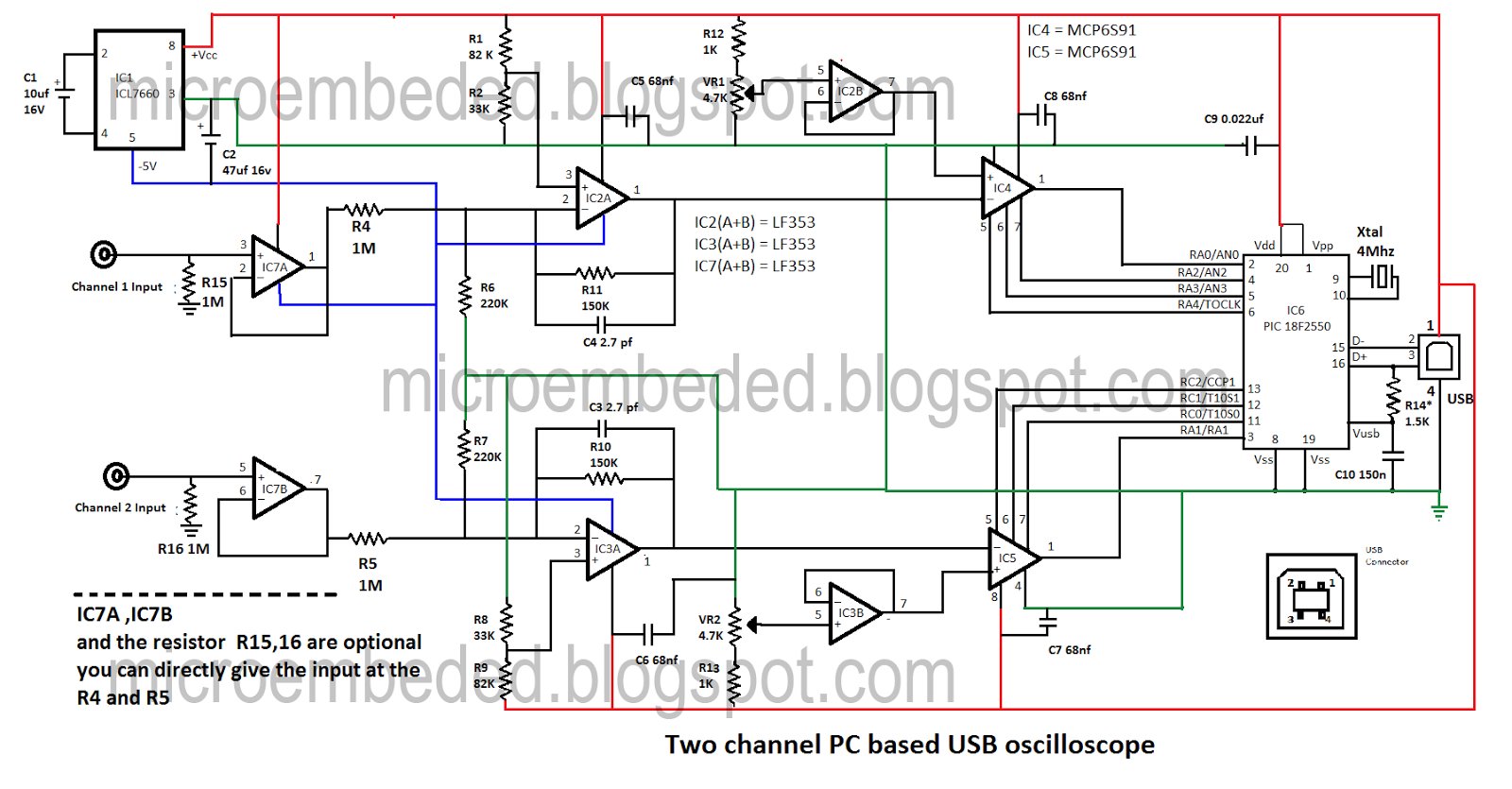
Installation of the USB driver.
1. If everything is fine, plug the oscilloscope with a USB cable to your PC (running Windows 98SE or higher version). A “new hardware detected–USB2-MiniOscilloscope” dialogue box must immediately appear on the screen.
NOTE:- The driver for this oscilloscope is not for windows 7 or vista.
- What is the maximum input voltage range of this oscilloscope?
The oscilloscope operates with an input voltage of ±16V. - Can I use PIC18F2445 instead of PIC18F2550?
Yes, you can use IC18F2445 in place of PIC18F2550. - How are negative input signals handled in this circuit?
Voltage-shifting amplifiers LF353 are used to shift input signals to the 0-5V range because the MCP6S91 amplifiers accept only positive signals. - What software tools are required to program the microcontroller?
MPLAB 8.70 along with MPLAB_C18 is used as the software tool for development. - Does this project work on Windows 7 or Vista?
No, the driver for this oscilloscope is not for Windows 7 or Vista. - What is the function of the ICL7660 component?
The ICL7660 is used to feed -5V to the LF353 op-amps which need a symmetrical supply voltage. - How many channels does this oscilloscope support?
This is a two-channel PC-based oscilloscope. - What is the operating speed of the microcontroller?
The CPU runs up to 12 MIPS.
