


Introduction
The idea of this project is to control (switch off/on) two power sockets with a computer by using its USB port. I’ve chosen USB in first place because I wanted to experiment with the PIC18F4550 microchip’s microcontroller, and secondly because the power supplied by this port (500mA) is enough to activate a relay without any additional power supply.
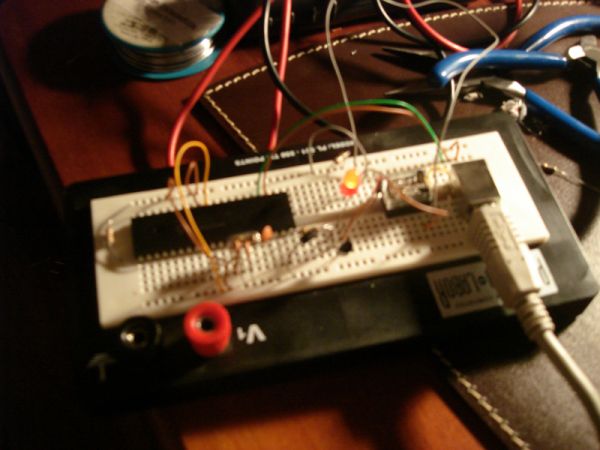
The firmware is based in SIXCA USBDAQ which is in turn based on microchip’s CDC sample. USBDAQ is extremely easy to use. It implements a very simple set of ASCII commands to turn on/off the digital outputs, that I use to control the two relays. I just needed to adjust the bMaxPower in order to negotiate the 500mA with the host, and I also changed the vendor ID and the name of the device to USocket.
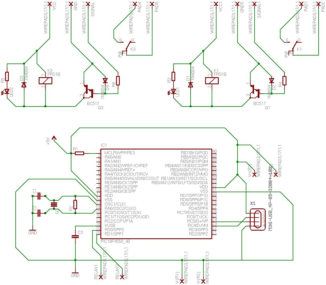
I’ve also made the schematic and board design of the circuit with Eagle, but I never used it since I made it on a strip board  , so if you plan to use it please double check everything before.
The whole project including PIC firmware and Eagle files is available for download. You are free to use or modify it as you like, but please verify Microchip’s CDC sample license if you plan to use it for commercial applications.
Disclaimer: This project involves high voltage electricity. You should not attempt this project unless you are comfortable with basic concepts of AC and DC electricity, induction, and reading circuit schematics. You and your adult supervisor are responsible for your safety when doing this project!
Advice: Despites the high voltage part of the circuit is virtually isolated from the controller circuit by relays, these devices always represents a risk of mechanical failure and they can possibly damage your equipment or even cause physical injuries, so we (the author or the webmasters) are not responsible of any lose or damage.
The Circuit
Pretty much the same as USBDAQ but two (identical) sub-circuits were added to control the relays. A Darlington-transistor is used to protect the hardware. Once again, the idea was obtained from the web (thanks to google) and here is the link to the original article.
The PCB is divided in 3 little boards, for commodity and socket case space issues. (I’ve used only 2 strip boards in the actual prototype).
List of materials:
- IC1 – PIC16F4550 Microchip’s micro-controller (datasheet)
- Q2 – Crystal 20Mhz
- R1 – Resistor 4.7K
- R2 – Resistor 1M
- R3, R5 – Resistors 150
- R4, R6 – Resistors 100K
- K1, K3 – 5v Relays. I’ve used FBR211 by Fujitsu (datasheet)
- D1, D2, D3. D4 – Diodes 1N4004
- Q1, Q3 – BC517 Darlington-transistors (datasheet)
- LED1, LED2 – Regular leds
- C1, C2 – Capacitors 22pF
- C3 – Capacitor 470pF
- X1 – Mini-USB Connector Type B (datasheet)
PIC Firmware
Here is what I needed to modify from the original SIXCA USBDAQ:
I set bMaxPower to 250, which means 500mA. The power provided by hosts and hubs is twice the value of bMaxPower field, but in reality they are likely to allocate either 100 or 500 milliamperes rather than the specified amount.
Programming the PIC
I’ve used WinPic800 to program the PIC. Here is a screenshot of the parameters I used to program it.
Commands
I didn’t modified any of the USBDAQ commands. They are all available but I only need to use these 4 commands:
- *A01 (activate relay 1)
- *A00 (deactivate relay 1)
- *A11 (activate relay 2)
- *A10 (deactivate relay 2)
All the commands are followed by an enter (chr(13) or ‘\n’).
For more detail: USocket – USB controlled Socket with PIC18F4550
Related projects
PICDEM FS USB CDC Evaluation Board using PIC18F4550 with Proteus Simulation
Introduction The PICDEM FS USB CDC Evaluation Board is a practical microcontroller project built around the PIC18F4550, designed to demonstrate USB communication...
Peripheral Tutorials · PIC18F4550PICDEM FS USB Mass Storage Device using PIC18F4550 with Proteus Simulation
Introduction This microcontroller project demonstrates how to simulate a USB Mass Storage Device (MSD) using the PIC18F4550 in a Proteus simulation environment....
Development Boards & Kits · PIC18F2550Pinguino Project: A PIC Microcontroller Based Arduino
This is a complete tutorial to make a PIC Microcontroller based Arduino. This is a complete tutorial to make PIC microcontroller based...
Communication & Interfacing · PIC18F4520CAN FD Node based on a PIC18 Microcontroller
The introduction sets the stage for an embedded systems project that involves developing a Embedded C CAN FD project using the MCP2517FD...
Communication & InterfacingLAN9662 Gigabit Switch: Optimized for Industrial Ethernet
Introduction It should come as little surprise therefore that one element of what is now more commonly referred to in some circles...
Communication & InterfacingPIC Microcontroller: Fundamentals & Applications for Students
Introduction Microcontrollers are the key components in the embedded systems market. A variety of embedded systems was formed and developed after the...

Ibrar Ayyub
I am an experienced technical writer holding a Master's degree in computer science from BZU Multan, Pakistan University. With a background spanning various industries, particularly in home automation and engineering, I have honed my skills in crafting clear and concise content. Proficient in leveraging infographics and diagrams, I strive to simplify complex concepts for readers. My strength lies in thorough...