
Summary of In-Circuit debugger, created by E.E. Atanasios Melimopoulos using PIC16F628 microcontroller
This article describes the "INSIDER," a custom, low-cost In-Circuit Debugger (ICD) designed to overcome limitations of standard PIC debuggers. Created by Atanasios Melimopoulos, it features a 1-bit interface for maximum I/O flexibility, operates independently of target clock speeds and PIC types, and provides electrical isolation between the PC and the target hardware. The project utilizes a simple circuit design compatible with Hyperterminal via serial ports.
Parts used in the INSIDER:
- Double side 1"x 2" PCB
- 18pin DIP 16F628 PIC microcontroller
- Dual-optocoupler
- LEDs
- Pushbutton
- Resistors
- Serial connector
This project was sent by Electrical Engineer Atanasios Melimopoulos (Copyright (c) June 15, 2007)
INTRODUCTION:
In-Circuit-Debuggers, as you may already know, have become the PIC’s debugging standard tool for many programmers because it’s easy use and handy interface to the target picplaced- board. They come with MPLAB plug-ins that provides a full rich set of commands and functions in order to debug your code in real time.
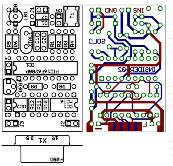
After hours of using some brands of ICDs, ICD2, etc. on different projects, I faced some hardware situations where the two pin interface ICD <-> PIC becomes annoying and sometimes difficult to work around. Apart from the fact that your target pic must run at selected clock frequencies that allows the ICD-Uart baudrate multiplier to fit. Also, some pics do not allow the same on-hook commands upon which ICDs are based. There is no electrical isolation between the pic-target board and the USB/Serial PC-GND interface.
Thinking about it, I decided to build the INSIDER, based on the following:
- 1Bit Interface placed on ANY I/O selected spare pin (or carefully shared). ICD 2bit interface is too much, usually on 12Fxxx 8-pin pics where there are only 6 I/O pins. Also on bigger pics, like 16Fxxx and 18Fxxxx where the RB port is the most useful, the fact that RB6-RB7 are forced to be the 2bit ICD interface, may goes against your hardware I/O connections and sometimes you can’t share their use.
- 1Bit Interface independent of the target PIC clock speed from 20KHz to 50MHz. ICD 2bit interface communicates to the target pic via serial ASCII link, that’s why the pic clock freq must be close to an integer multiple of the chosen baudrate.
- 1Bit Interface independent of the target PIC type (12Fxxx, 16Fxxx, 18Fxxxx) ICD commands and features are based on some bootstrap routines that Microchip places on most of its MPU types. But depending of the devices class, family and generation, this routines differs and so the ICD implementation of this functions.
- Electrical Isolation between the target PIC hardware and the PC workstation. PICs MCU are very useful on AC-line applications where the pic floats driving a MOSFET HBridge PWM converter or a Triac controlled power assembly, etc. That’s why it is so important to isolate the PC from the Target-PIC using an isolated connection ICD tool.
- Small, easy to build, easy PC interface and very easy to use. With a double side 1″x 2″ PCB, just one 18pin dip 16F628 pic, a dual-optocoupler, leds, a pushbutton, some resistors, serial connector, etc. I think this is a small and easy to build circuit. With no more than 10 well designed commands and the most basic interface available: Hyperterminal using the PC serial-Ports.
Against some opinions, PC serial comm ports are not obsolete, my Dual Core PC desktop has two and my Core 2 Duo Laptop (HP nx6320) has one. Of course I could place an USB-Uart bridge chip in order to use the PC USB port (maybe later) and you can find a handy PCI card serial port for your Desktop PC. (USB-serial-port cable doesn’lt work).
For more detail: In-Circuit debugger, created by E.E. Atanasios Melimopoulos using PIC16F628 microcontroller
-
What problem does the INSIDER debugger solve compared to standard ICDs?
It overcomes issues like the restrictive 2-pin interface, dependency on specific clock frequencies, lack of electrical isolation, and incompatibility with certain PIC families. -
How many pins does the INSIDER use for the interface?
It uses a 1-bit interface placed on any selected spare I/O pin or a carefully shared pin. -
Is the INSIDER dependent on the target PIC clock speed?
No, the 1-bit interface is independent of the target PIC clock speed, working from 20KHz to 50MHz. -
Does the INSIDER support different types of PIC microcontrollers?
Yes, it works independently of the target PIC type including 12Fxxx, 16Fxxx, and 18Fxxxx families. -
Why is electrical isolation important for this project?
Isolation is crucial for AC-line applications where the PIC floats while driving MOSFET HBridge PWM converters or Triac controlled power assemblies. -
What software interface does the INSIDER use to communicate with the PC?
It uses the most basic interface available: Hyperterminal using the PC serial ports. -
Can USB-serial-port cables be used with this debugger?
No, the text states that USB-serial-port cables do not work; a dual-core desktop with serial ports or a PCI card is recommended. -
Who created the INSIDER debugger?
The project was created by Electrical Engineer Atanasios Melimopoulos.

