


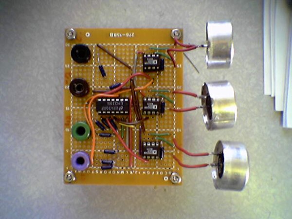
The ultrasonic position system uses ultrasonic transmitters/receivers to triangulate position of the robots used in GE423. Each of three transmitters uses a distinct frequencies: 23 kHz, 31 kHz, and 40 kHz. The 2812 DSP is used to measure signal timing and calculate position based on these values. The design of the electronics, as well as discussion of the software development is presented below.
1.0 Hardware
1.1 Ultrasonic Transmitters/Receivers
Details on the components of the transmit circuit can be found in the subsection below:
1.2.1 Frequency Generation
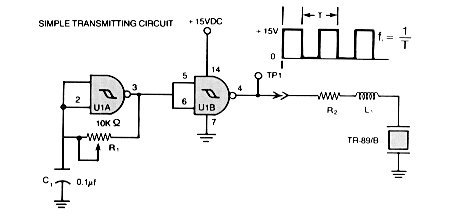
The transmit circuit take from the Massa Website looks like:
1.2.2 555 Timer Circuit
The documentation for the 555 timer can be found here. An a picture of how it is wired can be
Source:http://www.williamson-labs.com/480_555.htm
Using the handy calculator for Ra, Rb, and C found here, Ra=100k ohm, Rb=200k ohm, and C=2.2 mircoF.
1.2.3 Driver Signal Circuit
The 35 Vdc supply is manufactured by Ultravolt, part number 1/4Aa24-P30. This supply is actually a 0-250 Vdc supply that uses a potentiometer to control voltage output.
Related projects
Voltage Measurement with A PIC Microcontroller
Voltage Measurement with PIC Microcontroller articulates a methodical framework for facilitating analog voltage measurement using the PIC18F4520, an advanced member of Microchip’s...
Development Boards & KitsUltra-Low Power: Microcontroller Standby Current to 130uA with OPEnS Power Control Board
At the OPEnS Lab, a key focus for our projects is achieving exceptionally long battery life. This was particularly true for the...
Development Boards & KitsAn Integrated Approach to Developing Applications with Microchip PIC Microcontrollers
1. Introduction In our daily lives, a variety of devices such as telephones, household appliances, and cars incorporate "smart" electronics, typically manifested...
Development Boards & KitsMicrocontroller-Driven AC Voltage Control with Soft Start Feature
1. INTRODUCTION PWM-based AC voltage controllers find extensive application in uninterruptible power supplies (UPS) and high-power flexible AC transmission systems. This variable...
Development Boards & KitsPIC Microcontroller-Based IC Tester for Efficient Integrated Circuit Verification
1. INTRODUCTION Within the electronics industry[1], as circuit complexity undergoes a drastic increase and the demand for higher reliability rises, a significant...
Development Boards & Kits · PIC16F887Hands-On Microcontroller Projects: BK300 Development Board Featuring PIC16F887 Chip Lab
1. INTRODUCTION The study of microcontroller systems is experiencing a global surge across various fields within science, engineering, and technology departments of...

Ibrar Ayyub
I am an experienced technical writer holding a Master's degree in computer science from BZU Multan, Pakistan University. With a background spanning various industries, particularly in home automation and engineering, I have honed my skills in crafting clear and concise content. Proficient in leveraging infographics and diagrams, I strive to simplify complex concepts for readers. My strength lies in thorough...