


Summary of Two way Simple Very Small Telephone Exchange
This project is a very small two-line telephone exchange using a PIC16F84A microcontroller providing full bidirectional intercom between two ordinary telephones; when one goes off-hook the exchange rings the other and connects them. Power is from a 230 V supply with a step-down transformer producing multiple voltages; the controller interfaces two SLIC modules.Parts used in the Very Small Telephone Exchange:
- Step down transformer (230 V to 30 V, 15 V & 100 V)
- Two bridge 1 A rectifiers
- 7805 5V regulator
- 7812 12V regulator
- 1000 µF, 35 V electrolytic capacitor
- 1000 µF, 16 V electrolytic capacitor
- 150 mA fuse and fuse holder
- Necessary wires and AC supply wiring
- 2SC945 transistors x3
- 1N4007 diode x1
- 1N4148 diodes x2
- LED x1
- 4.7 µF (16 V) capacitors x4
- 22 pF capacitors x2
- 10 K resistors x4
- 4.7 K resistors x4
- 330 ohm resistor x1
- 12 V telephone relay x1
- Necessary wires for controller/SLIC connections
- PIC16F84A microcontroller with firmware version 1.00
- Two SLIC modules (each with TN, SD, RG connections)
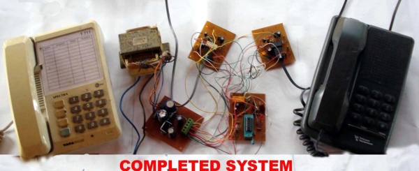
This is a very small telephone exchange attached only two ordinary Tele phones. Fully bi-directional facility with an intercom system. When a phone is in off hook condition , Exchange will detect it & send ringing pulse to other phone. When it will be picked up , the connection will be established between both phones. This will be taken place vice-versa.
Micro Controller = PIC16F84A
Firmware version = 1.00
Power Supply = 230 v
 Power Supply Unit
The Power Supply Unit.
This is used normal step down transformer (400ma) for generating three type of deference voltages & 100 AC volt for rigging.
It doesnt provided a PCB pattern for the power supply unit. So a Vero board can be used to build the unit.
Parts List :
1.Step down transformer ( 230 V to 30 V , 15 V & 100 V )
2.Two bridged 1 A rectifiers
3.7805 5V regulator
4.7812 12V regulator
5.1000 uf 35 V
6.1000 uf 16 v
7.150 ma fuse & its holders.
8.Necessary Wires & a wire code for AC supply.
The controlling unit ( Exchange )
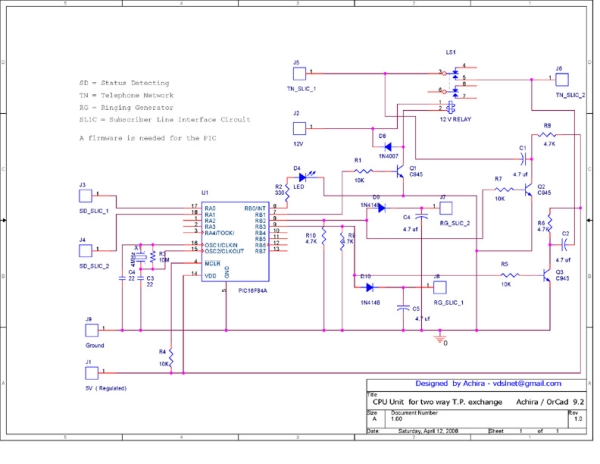
This circuit is base on PIC16F84A microcontroller. Two slimier SLIC are connected to The controlling unit. It needs to identify following connections on the controlling unit circuit diagram.
TN_SLIC_1 & TN_SLIC_2
SD_SLIC_1 & SD_SLIC_2
RG_SLIC_1 & RG_SLIC_2
One SLIC connections should be marked as,
1. TN_SLIC_1
2. SD_SLIC_1
3. RG_SLIC_1
Other SLIC connections should be marked as,
1. TN_SLIC_2
2. SD_SLIC_2
3. RG_SLIC_2
These connections should be connected as on the controlling unit circuit diagram.
 Parts List :
Transistors
1. 2SC945 x 3
Diodes
1. 1N4007 x 1
2. 1N4148 x 2
3. LED x 1
Capacitors ( 16 V )
1. 4.7 uf x 4
2. 22 pf x 2
Resistors
1. 10 K x 4
2. 4.7 K x 4
3. 330 x 1
Other Parts
12 V telephone rely x 1
Necessary wires
PIC16F84A with the firmware
For more detail: Two way Simple Very Small Telephone Exchange
Quick Solutions to Questions related to Very Small Telephone Exchange:
- What microcontroller is used in the exchange?
The PIC16F84A microcontroller is used with firmware version 1.00. - How many telephones can this exchange support?
It is attached to two ordinary telephones only. - How does the exchange detect and connect calls?
When a phone goes off hook the exchange detects it and sends a ringing pulse to the other phone; picking up establishes the connection bidirectionally. - What voltages does the power transformer provide?
The step down transformer provides 30 V, 15 V, and 100 V AC outputs. - Are PCB patterns provided for the power supply unit?
No PCB pattern is provided; a Vero board can be used to build the power supply unit. - What SLIC connections are required for each line?
Each SLIC requires TN_SLIC_x, SD_SLIC_x, and RG_SLIC_x connections (for SLIC 1 and SLIC 2 respectively). - Which relay is used in the controlling unit?
A 12 V telephone relay is used in the controlling unit. - What diodes are listed in the parts for the controller?
The controller parts list includes one 1N4007 and two 1N4148 diodes plus one LED. - What capacitors are needed for the controller section?
The controller uses four 4.7 µF (16 V) capacitors and two 22 pF capacitors. - What resistors are required for the controller?
The controller requires four 10 K resistors, four 4.7 K resistors, and one 330 ohm resistor.
Related projects
PIC Stepper Motor Controller using PIC16F84A with Proteus Simulation
Introduction Stepper motors are widely used in embedded systems and DIY electronics projects where precise position control is required. This PIC Stepper...
Programmers & ICSP · PIC16F84APIC Musical Doorbell using PIC16F84A with Proteus Simulation
IntroductionThis microcontroller project demonstrates a musical doorbell built around a PIC16F84A and a simple piezo sounder.Using two push buttons, the system allows...
Beginner Tutorials · PIC16C84Exploring the World of PIC Microcontrollers: An Architectural Overview
A Peripheral Interface Microcontroller (PIC), developed by General Instruments Microcontrollers in 1993, operates under software control and is programmed to execute various...
Wireless & IoTExploring Various Applications of Microcontrollers: A World of Tiny Brains
Exploring Various Applications of Micro Controller Microcontrollers have become ubiquitous in the modern world with applications in nearly every industry. This student...
Wireless & IoTIntelligent Sips: Revolutionizing Dining with the SmartCup
Abstract The SmartCup Attachment is a comprehensive system designed for restaurants to monitor the liquid levels in their customers' cups. This system...
Wireless & IoTMaximizing Wi-Fi Capabilities with the Explorer 16 Development Board
As society progresses, the necessity for wireless communication is evolving from a mere luxury to an essential requirement. Wi-Fi, extending beyond conventional...

Ibrar Ayyub
I am an experienced technical writer holding a Master's degree in computer science from BZU Multan, Pakistan University. With a background spanning various industries, particularly in home automation and engineering, I have honed my skills in crafting clear and concise content. Proficient in leveraging infographics and diagrams, I strive to simplify complex concepts for readers. My strength lies in thorough...