
Summary of A PIC frequency counter operating up to about 50 MHz. usnig pic microcontoller
This project describes a PIC-based frequency counter capable of measuring signals from 1Hz to approximately 50MHz. It utilizes an LCD for display and relies on Timer1 in 16-bit counter mode to count input signal edges, while Timer0 measures the precise one-second timing period using a 4MHz crystal oscillator. The system employs interrupt-driven software written in MikroC for the PIC16F877A microcontroller, featuring an LED status indicator and in-circuit programming support via ICSP.
Parts used in the PIC Frequency Counter:
- LCD (configured in 4-bit mode)
- PIC Microcontroller (16F877A or compatible with Timer0/Timer1)
- 4MHz Crystal Oscillator
- Two Capacitors (for oscillator tuning)
- LED (for status indication)
- ICSP Connector (for in-circuit programming)
This PIC frequency counter project uses an LCD to display the frequency and PIC timer 1 to measure the input signal and Timer0 to measure the timing period.
It uses Timer 1 in 16 bit counter mode to count the input signal edges and overflows of the counter are accumulated to give the total count in multiples of 65536.Adding the current value of the counter at the end gives the total count.
 The crystal oscillator is chosen to be 4MHz (Fosc) so that the processor internal clock is 1MHz (Fosc/4). All you do is count 1e6 processor clocks (Timer0) to give a 1second count period.
Since the measurement time is 1 second the final count is actually the frequency of the input signal.
Specification
| Min frequency | 1Hz |
| Max frequency | ~50MHz (limited by input pin characteristics).(Tested using TTL oscillator at 20MHz). |
| Input signal level | TTL |
Note: The exact maximum operating frequency is determined by the PIC input pin characteristic.
| Compiler | Mikroelectronika MikroC Compiler Free! |
| Target | 16F877A (retargetable to other PICs that have TMR1) |
| Software level | Advanced. |
| Software notes | Interrupt Driven counting and time measurement. |
| Hardware level | Easy. |
| Hardware notes | None |
| Project version | 1.03 |
| Project files | Enter your details to get the Download Link and get the microcontroller newsletter: (Note: Your email is safe it will never be sold or rented). Note: Check your email for the project code download link. |
For the general theory of operation of this circuit and notes on frequency counting of this pic frequency counter click here.
Pic frequency counter Hardware
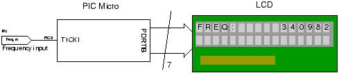
The hardware is simple and the main blocks are shown in the diagram below.
The LCD is used in 4 bit mode interface so you only need 4 data lines and three control lines and it then fits into a single 8 bit port.
The crystal oscillator is simply a crystal and two capacitors connected to the PIC oscillator port at OSC1 and OSC2. The capacitors can both be fixed at the same value unless you want to tune it using a frequency reference. If you don’t have an accurate reference then use fixed capacitors.
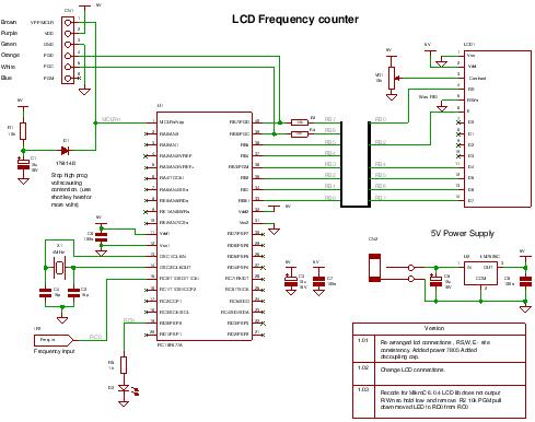 The PIC micro can be any type that has Timer 0 and Timer 1 hardware modules and and has enough memory to hold the program ~1.6k words.
The LED is toggled to indicate that the processor is alive – so if there is no input signal you can tell that the software is working. Also if there is no input signal the the LCD displays a flashing zero.
You can program the PIC in circuit through the ICSP connector in circuit.
Description
To time a 1 second count Timer0 is used. Since the main clock is running at 4MHz then the processor clock (Fosc/4) is 1MHz which is the rate that Timer0 is set-up to use i.e. the internal clock. Therefore we need to get a 1 second count using that timer. Since the timer is only 8 bits long you can use the fact that an interrupt is generated when it overflows – you can then count these overflows to get near to 1e6 counts.
Since the overflow occurs every time that the counter passes 256 we need to count 1e6/256 overflows
For more detail: A PIC frequency counter operating up to about 50 MHz.
- How is the measurement time determined?
A 1 second count period is achieved by counting 1e6 processor clocks using Timer0. - What is the maximum operating frequency?
The max frequency is approximately 50MHz, limited by the input pin characteristics. - Which compiler is recommended for this project?
The project uses the Mikroelectronika MikroC Compiler Free! - How does the system handle timer overflows?
Overflow events from the 8-bit Timer0 are counted to accumulate the total 1 second duration. - Can the microcontroller be programmed in circuit?
Yes, the PIC can be programmed in circuit through the ICSP connector. - What indicates that the processor is alive?
An LED is toggled to show activity, and the LCD displays a flashing zero if no input signal is present. - How many data lines are required for the LCD interface?
The LCD operates in 4-bit mode requiring only 4 data lines and three control lines. - What happens if there is no input signal?
The LCD displays a flashing zero while the LED continues to toggle to indicate software operation.

