


Summary of Interfacing of PIC12F675 with DS1307 (RTC) code and Proteus simulation
This article details the software-based I2C interfacing of a DS1307 Real-Time Clock with a PIC12F675 microcontroller using C language in MPLAB. Since the PIC lacks hardware I2C, a software module was implemented. The system displays RTC data on an LCD and includes a Proteus simulation demonstrating correct time updates and bus debugging via an I2C tool.Parts used in Interfacing DS1307 RTC with PIC12F675:
- DS1307 RTC
- PIC12F675 microcontroller
- LCD
- GP4 pin (SDA)
- GP5 pin (SCK)
- 10K resistors
- MPLAB v8.85
- HI-TECH C v9.83 compiler
- Proteus v7.10
- I2C Debugger Tool
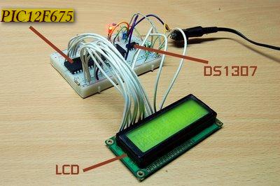
This DS1307 RTC has i2c based interface and PIC12F675 doesn't have any built in i2c modules, so software i2c module is created in the code. This code is written in C language using MPLAB with HI-TECH C compiler. You can download this code from the 'Downloads' section at the bottom of this page.
It is assumed that you know how to interface LCD with PIC12F675 microcontroller. If you don't then please read this page first, before proceeding with this article. It is also assumed that you know how to create software i2c module in PIC12F675 , if you don't then please read this page first.
The result of simulating the code in Proteus is shown below.
In the above circuit[1], GP4 pin is being used as SDA pin and GP5 pin is the SCK pin. Both of these pins are pulled up using 10K resistors as required for i2c protocol. DS1307 RTC is the slave device, while PIC12F675 is configured to be the master. LCD is also attached with PIC12F675, just to show the values received from the RTC, otherwise it is not required in this circuit. Proteus provides an 'I2C Debugger Tool' which is attached on the SDA and SCK pins in the above circuit, this debugger shows all the activity on i2c bus[2]. It is attached in the circuit just for debugging purposes.
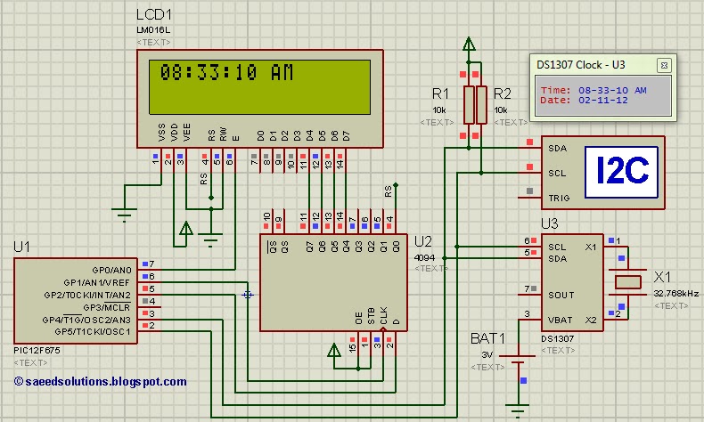
In the code, in the start a command is sent to DS1307 to set time to 8:32:59 AM and date to 2/11/12. After this, DS1307 starts to increment it's time after every second. Then new time is read from DS1307 RTC after every second and displayed on the LCD. Figure 1 was taken when time was 8:33:10 AM, which is correctly displayed on the LCD.
Code
The code for the main function is shown below.
Downloads
DS1307 RTC interfacing with PIC12F675 code was compiled in MPLAB v8.85 with HI-TECH C v9.83 compiler and simulation was made in Proteus v7.10. To download code and Proteus simulation click here.
For more detail: Interfacing of PIC12F675 with DS1307 (RTC) code and Proteus simulation
Quick Solutions to Questions related to Interfacing DS1307 RTC with PIC12F675:
- How is the I2C interface handled since PIC12F675 lacks built-in modules?
A software i2c module is created in the code. - What programming language and compiler are used for this project?
The code is written in C language using MPLAB with HI-TECH C compiler. - Which pins are assigned as SDA and SCK?
GP4 pin is used as the SDA pin and GP5 pin is the SCK pin. - What value do the pull-up resistors have for the I2C protocol?
Both SDA and SCK pins are pulled up using 10K resistors. - What role does the LCD play in this specific circuit?
The LCD is attached just to show values received from the RTC and is not required for the core function. - What tool does Proteus provide for debugging the I2C bus activity?
Proteus provides an 'I2C Debugger Tool' which shows all activity on the I2C bus. - What initial time and date were set in the code command?
The code sends a command to set the time to 8:32:59 AM and the date to 2/11/12. - How often is new time read from the DS1307 RTC?
New time is read from the DS1307 RTC after every second.
Related projects
PIC 12F675 Programmable 12V Battery Monitor
Being an active outdoor guy, I have a few different types of 12V lights and a variety of battery types. - For...
Audio, Sound & Radio · PIC12F675Audio CRO using PIC12F675 Microcontroller
This project is a miniature Audio CRO. For those not familiar with the abbreviation "CRO," it means "Cathode Ray Oscilloscope" and this...
Development Boards & Kits · PIC12F675DIY $1 PIC 12f675 JDM Programmer (Cheap and Easy)
Hi EveryBody i am Again Doing something. and it is with PIC's! Almost Everybody do not want a Big Arduino in their...
Communication & Interfacing · PIC18F4520CAN FD Node based on a PIC18 Microcontroller
The introduction sets the stage for an embedded systems project that involves developing a Embedded C CAN FD project using the MCP2517FD...
Communication & InterfacingLAN9662 Gigabit Switch: Optimized for Industrial Ethernet
Introduction It should come as little surprise therefore that one element of what is now more commonly referred to in some circles...
Communication & InterfacingPIC Microcontroller: Fundamentals & Applications for Students
Introduction Microcontrollers are the key components in the embedded systems market. A variety of embedded systems was formed and developed after the...

Ibrar Ayyub
I am an experienced technical writer holding a Master's degree in computer science from BZU Multan, Pakistan University. With a background spanning various industries, particularly in home automation and engineering, I have honed my skills in crafting clear and concise content. Proficient in leveraging infographics and diagrams, I strive to simplify complex concepts for readers. My strength lies in thorough...