
Summary of Dspic-Servo Project using PIC30F4012 microcontroller
This project creates an inexpensive desktop CNC servo drive using a PIC30F4012 microcontroller and a power op-amp. It interfaces with a PC via parallel port quadrature signals, utilizing a serial connection for PID tuning. The system monitors encoder feedback to control DC brushed motors, offering adjustable parameters like deadband, max output current, and fault error detection to optimize positioning accuracy and prevent mechanical damage.
Parts used in the Dspic-Servo:
- PIC30F4012 microcontroller
- Power operational amplifier
- DC brushed motor
- Parallel port (PC interface)
- Serial port (for tuning)
- DSPIC EEPROM
- Encoder
- C30 compiler
Project Description
This project was developed as an inexpensive way to drive small dc brushed motors as positioning servos for use on a desktop sized CNC machine. The board is interfaced to the PC through 2 pins of a parallel port. The drive signal on these pins is known as quadrature drive.
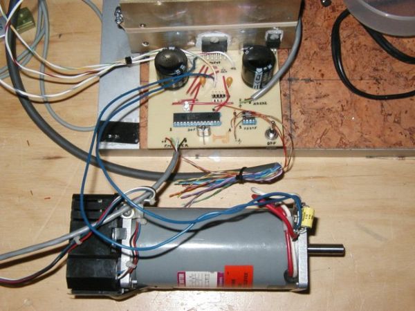
The power stage consists of a power op amp driven in constant current mode. The internal PIC processor ( a 30f4012 from Microchip ) is programmed in C through the C30 compiler and the Microchip IDE. The servo loop parameters are programmed through a serial port connection and are saved in the dspic eeprom. Once set for a particular drive, they should not need to be changed.
A YouTube video by Ted Maczulat.
The serial programming interface is used to tune the PID and other servo loop parameters to optimize the performance in a particular application. The serial port runs at a fixed baud rate of 9600N81. Any terminal program such as minicom, gtkterm, or hyperterminal may be used to talk to the dspic-servo. On powerup you will see the following:
Powerup...i/o...uart...timer...pwm...pid...encoder...capture...done

dspic-servo by L. Glaister
(c)25-Sept-2006 by VE7IT

using setup from eeprom.. ? for help

Current Settings:
servo enabled = 1
(p) = 0.020000
(i) = 0.000000
(d) = 0.000050
FF(0) = 0.000000
FF(1) = 0.000000
dead(b)and = 1.000000
(m)ax output = 2.500000
(f)ault error = 1024.000000
(x)pc cmd multiplier = 3
(t)icks per servo cycle= 10
To change a value, type the cmd letter/number and then a value for example:
p0.03
The current values will be redisplayed with the new value set. The p,i,d, ff0 and ff1 values are standard loop gain parameters. You can reference the source code for a better explanation. The deadband parameter is the number of encoder counts the servo can be out of position without the servo loop taking any corrective action. The max output is the maximum current output allowed in amps and should be set for the particular motor you are using. This number can be up to 7 amps. The fault error parameter is used to set the number of counts the servo can be out of position before the drive gives up and indicates a drive fault. This is used to detect crashes and jammed axis or input command conditions beyound the capabilities of the motor. The pc command multiplier is useful for cases where you have a high resolution encoder on the motor and a PC that is limited in the number of pulses/second it can output. For most operation this number will be set to 1, but if you have trouble reaching the top speed you need from the drive, it may be helpful to set this number to a higher value. The internal servo loop works by keeping 2 counters. The first is the commanded position from the PC, the second is the actual position from the encoder. The servo loop of the drive attempts to keep these 2 numbers as close as possible to each other.
For more detail: Dspic-Servo Project using PIC30F4012 microcontroller
- How does the board interface with the PC?
The board is interfaced to the PC through 2 pins of a parallel port using a signal known as quadrature drive. - What processor is used in the power stage?
The internal processor is a 30f4012 from Microchip, programmed in C through the C30 compiler. - How are the servo loop parameters saved?
Parameters are programmed through a serial port connection and saved in the dspic eeprom. - What baud rate does the serial programming interface use?
The serial port runs at a fixed baud rate of 9600N81. - What is the function of the deadband parameter?
The deadband parameter defines the number of encoder counts the servo can be out of position without the loop taking corrective action. - What is the maximum current output allowed?
The max output value can be set up to 7 amps depending on the specific motor being used. - When should the pc command multiplier be increased?
This number may be set higher if you have trouble reaching top speed due to PC pulse limitations. - What triggers a drive fault indication?
A fault occurs when the servo is out of position by more than the count set in the fault error parameter.
