
Summary of 2 Digit 99 Seconds Timer
This 2-digit countdown timer is a microcontroller-based utility project designed for intervals up to 99 seconds. It features a 12V DC power supply, two 0.5-inch display segments, and a 12V SPDT relay for controlling external loads or alarms. The kit includes tactile switches for setting time and starting the countdown, along with LED indicators for power and relay status. Powered by a crystal resonator for accuracy, it uses terminal connectors for easy interfacing and includes onboard voltage regulation and reverse polarity protection.
Parts used in the 2 Digit Count Down Timer:
- Microcontroller
- Power supply input 12 VDC 200 mA
- Two 0.5″ display segments
- 12V SPDT relay
- Tactile switches (UP, DOWN, SET)
- Power and Relay-On LED indicators
- Terminal connectors
- Onboard regulator
- Crystal resonator
- PCB (72 mm x 81 mm)
- D1 diode for reverse polarity protection
- J3 connector for external switches
2 Digit Count Down Timer is a utility Count Down timer project for upto 99 seconds of countdown time. This project can find many uses in your shack and home. The relay output remains on during the Count Down period, allowing you to interface load or alarm that you want to keep it on for a certain amount of time (in seconds).
Specifications
- Microcontroller based design for greater accuracy and control
- Power supply input 12 VDC 200 mA
- Two 0.5″ display segments to display time
- 12V SPDT (Single Pole Double Throw) relay for alarm use
- Single key start and dual key alarm time set function
- Power and Relay-On LED indicator
- Terminal connectors for connecting power supply input and relay output to the PCB
- Onboard regulator for regulated supply to the kit
- Crystal resonator based design for better accuracy
- PCB dimensions 72 mm x 81 mm
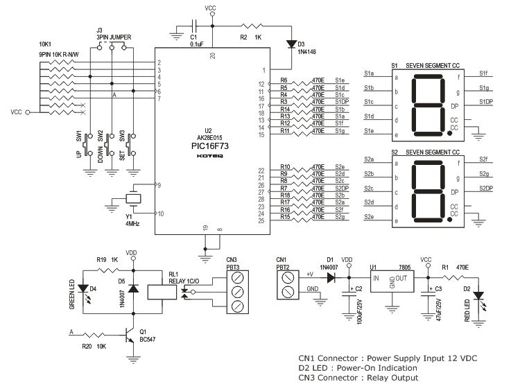
This is a microcontroller based 2 Digit (99 Seconds) Count Down Timer. This Count Down Timer is very easy to use and easy to configure. This project can find a lot of application areas where you need a device to remain ON (or OFF) for a certain period of time (upto 99 Seconds). Power to the circuit is applied at CN1 (12 VDC). D1 provides the reverse polarity protection to this kit. LED D2 confirms DC Power Supply to the board. S1 and S2 displays Count Down time. J3 provide an easy way of connecting external switches to this board. LED D4 confirms the relay status.
Operating Instructions:
The setting up of countdown period and START Function for this kit is accomplished with the help of 3 tactile switches shown as SW1, SW2 and SW3 in the schematic and labeled as UP, DOWN and SET on the PCB respectively.
- Setting Time : The default value is shown on display S1 and S2 respectively. You can change this value by simply pressing the UP and DOWN key.
- Start : You can start the Count Down by pressing SET key. When the Count Down starts the relay is energized, indicated with the glow of LED D4. Once the Display (S1 and S2) reaches 0 the relay is de energized.
Schematic
For more detail: 2 Digit 99 Seconds Timer
- What is the maximum countdown time of this project?
The project supports a countdown time of up to 99 seconds. - How do I set the countdown duration?
You can change the default value by pressing the UP and DOWN keys. - How do I start the countdown?
Pressing the SET key starts the countdown and energizes the relay. - Does the relay remain on during the countdown?
Yes, the relay output remains on during the countdown period until the display reaches 0. - What type of power supply does this kit require?
The kit requires a 12 VDC power supply at 200 mA input. - Can I connect external switches to this board?
Yes, J3 provides an easy way of connecting external switches to the board. - What ensures the accuracy of the timer?
The design uses a crystal resonator for better accuracy. - How is reverse polarity protected in this circuit?
D1 provides reverse polarity protection to the kit.
