


Summary of The Rock
This article details the design and construction of a dual-mode robot capable of object transport and light tracking. Controlled via Visual Basic over a serial port, the robot uses a PIC 16F877 microcontroller to manage four DC motors with PWM signals for variable speeds. It features multiple sensors for tilt, light, battery level, and collision detection, allowing it to maintain constant speed on inclines and stop safely when stuck. The project took four months and cost approximately $600, involving distinct phases from circuit design and component selection to programming and assembly.Parts used in the Dual-Mode Robot:
- PIC 16F877 Microcontroller
- 4 DC Motors
- 3 Motor Driver Circuits (H-bridge)
- MAX232 Wireless Circuit
- LM331 Component
- FM Transmitter and Receiver Modules
- Battery Power Source
- MC7805 Voltage Regulators
- Microswitches
- Photoresistors (Light Sensors)
- Tilt Sensor
- Stall Current Sensing Unit
- Battery Level Sensing Unit
- Limit Switches
- Touch Sensors
This robot is controlled by a visual basic program (through the serial port), and can move in three different velocities by a pulse width modulated (PWM) signal generated by a PIC microcontroller (16F877).
The robot can be operated in two modes, "normal control" and "light tracker" modes. In the normal control mode, the robot can carry objects sized from 3 - 18 cm from place to another within 150 m. whereas in the light tracker mode, it follows the light in a dark room.
Many sensors were used, such as light sensors; tilt sensor, stall current sensing, battery level sensing, and some limit switches and touch sensors used in the hand. It can keep its speed constant when it goes on a hill (tilted) and automatically turns the light on when it becomes dark dark. Also to keep the IC's safe, it disconnects the current when it's stuck and the hand stops when holding something.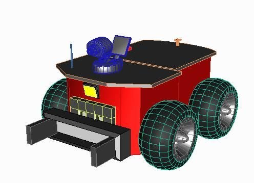
4 DC motors were used controlled by a PIC microcontroller 16F877 and 3 motor driver circuits.
It took about 4 months, and costs about 600$
Step 1: Design the Project
at the initial stage, a design of the project was provided. mainly, defining the block diagram; see the figure.
A more detailed Circuit Diagram is required at this stage, however, to facilitate this, the main modules identified were:
1. Microcontroller
2. Sensors
3. Motors
4. Wireless circuit
5. PC program.
A 3d Design was done as well, see the figure.
Step 2: Choose the Devices and Components
At this stage, the designer should choose the devices and components required to build the robot.
This includes: the wireless circuit (MAX232, LM331, FM transmitter and Receiver modules), motors (4 DC motors), motors drivers circuit (H-bridge), the microcontroller PIC (16F877), Battery, Voltage regulators (MC7805), Microswitches, Photoresistors, Tilt sensor ... etc.
It is important to understand the computability of these devices and how they work together.
Step 3: The Microcontroller
This step is the most important step. at the beginning, the codes that will be received and transmitted from the PIC should be identified.
Start connecting the components to the appropriate pins of the PIC, and program the microcontroller. This may require to build small circuits using the regulators, resistors, sensors ...etc.
Step 4: Write the PC Program
The program was written on visual basic.
The communication was established through the RS-232. Using MSComm to send the data to the microcontroller by configuring the settings (port number, baud rate, parity number of data bits, stop bits).
I used 8-bit data with one stop bit and parity at a baud rate 9600 bps.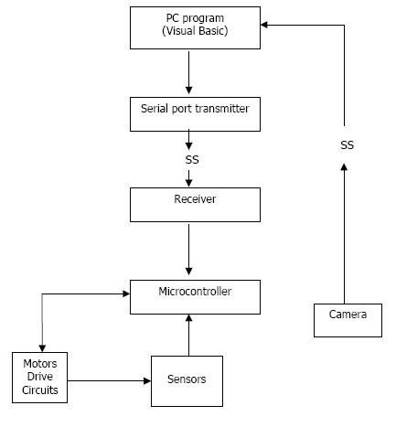
Step 5: Build the Body
A good design of the body is important. Also choosing the wheel arrangement, see the figure.
he robot was built after insuring that the programs are working fine. This step can be done before programming also.
For more detail: The Rock
Quick Solutions to Questions related to the Dual-Mode Robot:
-
How is the robot controlled?
The robot is controlled by a visual basic program sent through a serial port. -
What microcontroller generates the PWM signal?
A PIC microcontroller (16F877) generates the pulse width modulated signal to move the robot at three different velocities. -
Can the robot carry objects of varying sizes?
Yes, in normal control mode, the robot can carry objects sized from 3 to 18 cm within 150 meters. -
How does the robot behave in a dark room?
In light tracker mode, the robot follows the light source in a dark room. -
Does the robot adjust its speed on hills?
Yes, it keeps its speed constant when going up a hill using a tilt sensor. -
How are the ICs protected from damage?
The system disconnects the current when the robot gets stuck to keep the integrated circuits safe. -
What communication settings were used for the PC program?
The setup used 8-bit data, one stop bit, parity at a baud rate of 9600 bps via RS-232. -
How long did it take to build this robot?
The project took about 4 months to complete.
Related projects
Real-Time CAN-Based Vehicle Monitoring System with PIC MCU
INTRODUCTION The Controller Area Network (CAN) is a robust vehicle communication bus standard that was primarily developed for automobile applications but has...
Motors & RoboticsEasy Way to Learn Robotics Using Microcontrollers: A Beginner’s Guide
The title, "Easy Way to Learn Robotics Using Microcontrollers," promises an accessible entry point for those curious about the exciting world of...
Motors & Robotics · PIC16F877AEfficient Sun-Following Robot: A Solar Tracker with Microcontroller Control
Abstract The impending global challenge of dwindling non-renewable fuel resources underscores the urgency of transitioning towards renewable energy alternatives like solar power....
Motors & RoboticsInnovative Robotics: A Comprehensive Project Exploration
A DC motor functions as an electromechanical device, translating electrical signals into mechanical movements. The rotation of the motor correlates directly with...
Motors & RoboticsAdvanced Techniques for Fault Detection, Indication, and Protection in Induction Motors
1. INTRODUCTION The impact of microcontroller usage on our daily lives is remarkable. This versatile device is now prevalent in various control...
Motors & RoboticsExploring Versatility: GSM-Based Robotic Vehicle Technology
Introduction To Robotics The term 'Robot' remains elusive, defying a precise definition due to its evolving usage. Initially, it referred to humanoid...

Ibrar Ayyub
I am an experienced technical writer holding a Master's degree in computer science from BZU Multan, Pakistan University. With a background spanning various industries, particularly in home automation and engineering, I have honed my skills in crafting clear and concise content. Proficient in leveraging infographics and diagrams, I strive to simplify complex concepts for readers. My strength lies in thorough...