
Summary of SIGNAL GENERATOR CIRCUIT PIC16F88 JAL CODE EXAMPLE
This article presents an incomplete signal generator circuit project using a PIC16F88 microcontroller controlled via 5V logic. The author notes the design is experimental and not final, suggesting future improvements with CD4051 analog switches and potentiometers for frequency adjustment. The core implementation relies on JAL code to sequence output pins through Port B, creating a waveform pattern with specific timing delays.
Parts used in the Signal Generator Circuit:
- PIC16F88 Microcontroller
- Analog Switch (CD4051)
- Potentiometer
- JAL Programming Software
In an experiment with some changes I use this circuit for the development of’m sending you. I could not work because it is not a final time. To put it in principle, be controlled by Pic-5V to +5 V… Electronics Projects, Signal generator Circuit PIC16F88 JAL Code Example “microchip projects, microcontroller projects, pic16f88 projects,
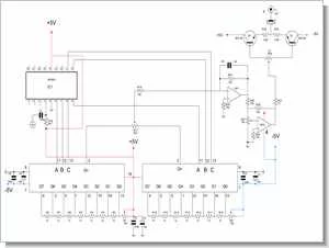
In an experiment with some changes I use this circuit for the development of’m sending you. I could not work because it is not a final time.
To put it in principle, be controlled by Pic-5V to +5 V analog switch between the output stage is based on the principle of giving. The future with analogue switch (CD4051) 4 units of work for removing a circuit will do better.
Would be best to send with the finished but at the moment I do not have time for this study. The reason for using 16F88 is for adjusting the frequency. Found another pic of the ADC can be used. ADC will connect the potentiometers with a frequency can be adjusted. I try to help to develop friends. Jal the spline drawing software.
Wishing to be useful and good work.
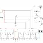
SIGNAL GENERATOR CIRCUIT SCHEMMATIC
JAL SOURCE CODE
include 16f88_4i
include jlib
port_b_direction = all_output
var byte x
x = 1

procedure sinyal is

port_b = 0b0100_0001  -- 1
delay_10us(x)
port_b = 0b0100_0010 --   2
delay_10us(x)
port_b = 0b0100_0011
delay_10us(x)          -- 3
port_b = 0b0100_0100   --  4
delay_10us(x)
port_b = 0b0100_0101   --  5
delay_10us(x)
port_b = 0b0100_0110    --  6
delay_10us(x)
port_b = 0b0100_0111   --   7
delay_10us(x)
port_b = 0b0100_0110     --  8
delay_10us(x)
port_b = 0b0100_0101    --   9
delay_10us(x)
port_b = 0b0100_0100  --  10
delay_10us(x)
port_b = 0b0100_0011     --  11
delay_10us(x)
port_b = 0b0100_0011       -- 12
delay_10us(x)
port_b = 0b0100_0000       -- 13
delay_10us(x)

port_b = 0b0000_1000       --  14
delay_10us(x)
port_b = 0b0001_0000      -- 15
delay_10us(x)

port_b = 0b0001_1000      --  16
delay_10us(x)
port_b = 0b0010_0000      --  17
delay_10us(x)
port_b = 0b0010_1000       --  18
delay_10us(x)
port_b = 0b0011_0000        --  19
delay_10us(x)
port_b = 0b0011_1000        --  20
delay_10us(x)
port_b = 0b0011_0000        --  21
delay_10us(x)
port_b = 0b0010_1000       --  22
delay_10us(x)

port_b = 0b0001_1000       -- 23
delay_10us(x)
port_b = 0b0001_0000       --  24
delay_10us(x)
port_b = 0b0000_1000       --  25
delay_10us(x)
port_b = 0b0000_0000       --  26
delay_10us(x)
end procedure

forever loop


sinyal

end loop


Source: SIGNAL GENERATOR CIRCUIT PIC16F88 JAL CODE EXAMPLE
- What microcontroller is used in this signal generator project?
The project uses the PIC16F88 microcontroller. - How is the frequency adjusted in this circuit?
The frequency can be adjusted by connecting potentiometers to the ADC of the microcontroller. - Can the ADC be used to adjust the frequency?
Yes, the author found that an ADC can be used to connect potentiometers for frequency adjustment. - What software is used for the spline drawing in this project?
JAL spline drawing software is used for the development. - Is the circuit described in the article fully finished?
No, the author states the circuit is not final and they do not have time to complete it yet. - What component is suggested to improve the circuit in the future?
The author suggests using four units of the CD4051 analog switch to remove a circuit and work better. - How does the microcontroller control the output stage?
The output stage is controlled by the PIC via a 5V to +5V analog switch principle. - What programming language is used for the source code?
The source code is written in JAL language.

