
Summary of PIC16F84 LED DISPLAY FREQUENCY COUNTER CIRCUIT
This article describes a DIY 6-digit frequency counter project designed to replace unavailable commercial units. The system utilizes a PIC16F84 microcontroller, a high-precision TCXO oscillator, and a TD7104P prescaler to measure frequencies between 1MHz and 300MHz (up to 400MHz with offset). It features a 7-segment LED display driven by TC4511 chips, capable of displaying signals from 100Hz minimum up to VHF/UHF bands like 144MHz and 433MHz.
Parts used in the PIC16F84 LED Display Frequency Counter:
- 7-segment LED 6-digit display
- TCXO 12.8MHz (1ppm) precision oscillator
- PIC16F84A-P20 microcontroller
- TD7104P Prescaler (÷ 8, ÷ 1)
- SC1906 preamp
- TC4511 drivers
- 5cm yellow alignment lead antenna
LED 6 digit display for rig frequency counter -Just as it may seem at frequency display of rig, and produced a dot LED-PD4435 counter, and make use of this in the future, and that the “sold out, there is… Electronics Projects, PIC16F84 LED Display Frequency Counter Circuit “microchip projects, microcontroller projects, pic16f84 projects,
LED 6 digit display for rig frequency counter -Just as it may seem at frequency display of rig, and produced a dot LED-PD4435 counter, and make use of this in the future, and that the “sold out, there is no plan of the re-arrival” and. To give up this, I made a 6-digit display using the 7-segment LED.
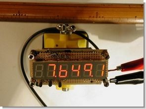
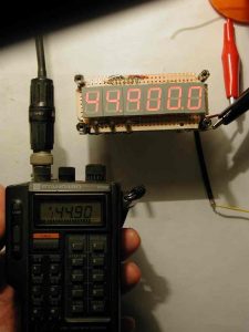
7 segment LED 6-digit precision TCXO 12.8MHz (1ppm), PIC16F84 with 1MHz ~ 300MHz (400MHz) IF offset frequency counter. TD7104P (Prescaler ÷ 8, ÷ 1) +2 SC1906 later in the preamp, PIC 16F84A-P20 count, LED display TC4511 drivers. Left; 144.90MHz handy 200mW transmission. ANT of the counter, lead 5cm yellow alignment there. And Central; 7,649.1 kHz SG signal. Minimum digit 100Hz. Zero blank function put, unnatural 0 of top disappear. And right; at 33.1688MHz, it is not. 433.17MHz handy 200mW transmission.
PIC16F84 FREQUENCY COUNTER PROJECT
The first stage prescaler counter TD7104P (÷ 8). Single power of PIC16F84A-P20 is, 433.17 ÷ 8 = 54.14MHz. However, close to 10kHz stand, display varies the limit. Only minutes to display low 1.2kHz, you’re counting mistake. If shaped by CMOS-TTL input waveforms of PIC, and extends to 60MHz or more probably.
Source: saturn.dti.ne.jp PIC16F84 LED Display Frequency Counter Circuit schematic pic assembly source code files alternative link:
FILE DOWNLOAD LINK LIST (in TXT format): LINKS-5056.zip
Source: PIC16F84 LED DISPLAY FREQUENCY COUNTER CIRCUIT
-
What is the primary purpose of this project?
To create a 6-digit display using 7-segment LEDs as an alternative to sold-out commercial dot LED counters. -
How does the circuit handle high-frequency inputs above 100kHz?
It uses a TD7104P prescaler for the first stage to divide the input signal before it reaches the microcontroller. -
What is the operating frequency range of this counter?
The device measures frequencies from 1MHz to 300MHz, extending to 400MHz with an IF offset. -
Which component provides the precise time base for the measurement?
A 12.8MHz TCXO with 1ppm precision serves as the timing reference. -
How are the 7-segment LEDs controlled in this design?
The display segments are driven by TC4511 driver chips connected to the PIC microcontroller. -
What function prevents unnatural zeros from appearing on the display?
A zero blank function is implemented to make leading zeros disappear naturally. -
What is the minimum digit resolution of the counter?
The minimum digit resolution is set to 100Hz.
