
Contents
hide
Summary of MOTION SENSOR USING PIR SENSOR MODULE WITH PIC MICROCONTROLLER AND WITHOUT MICROCONTROLLER
The article describes a simple motion-detection circuit using a PIR sensor module and a PIC12F635 microcontroller powered by four AA batteries (6 V) with a series diode to drop to ~5.4 V and provide reverse-polarity protection. The PIR module outputs about 3.3 V; this drives a BC547 NPN transistor whose collector is read by the PIC. With no motion the collector is at +5 V; when motion is detected the transistor saturates and the collector goes low. PIC12F635 runs on its internal 4 MHz oscillator with MCLR disabled and WDT off.
Parts used in the Motion Sensor Using PIR Sensor Module with PIC Microcontroller:
- 4 AA batteries (recommended alkaline)
- Diode (series for voltage drop and reverse polarity protection)
- PIC12F635 microcontroller
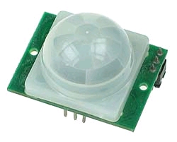
- PIR sensor module (pyroelectric sensor with Fresnel lens and SB0061 analog IC)
- NPN transistor BC547
- LM7805 regulator IC (optional if using 9 V battery)
- Jumper for trigger selection (H position)
The circuit diagram is quite simple. I have powered my circuit with 4 AA batteries that gives 6 V supply.
A diode is used in series to drop the voltage down to 5.4 V as the operating voltage for the PIC microcontroller should be below 5.5 V. Besides, the diode also provides the protection to the circuit in case of reverse polarity of the power supply. I have tested the circuit with NI-MH rechargeable batteries (that gives 4.8 V) and it worked, but I recommend to use the alkaline batteries (1.5 V each) for better performance. You can also use a 9 V battery but then you need a LM7805 regulator IC in your circuit.
 The output of the PIR sensor module is monitored through GP5 (pin 2) of PIC12F635. When the motion is sensed, this output is high at about 3.3 V (my sensor module has a 3.3V regulator IC on board). You could still use this voltage as a valid logic high for PIC12F635, but I preferred to use this voltage to drive the base of an NPN transistor (BC547) so that at the collector we will have the full swing of the logic voltages. Now, the microcontroller monitors the voltage at the collector of the transistor. During the normal condition, the transistor is cut off, and the collector output is at logic high (+5 V). When the motion is sensed, the high output from the sensor module saturates the transistor and the voltage at the collector drops down to logic low. The jumper selection for trigger is at H position, so the sensor output will remain active as long as the motion exists. Note that the PIC12F635 microcontroller uses the internal clock oscillator at 4.0 MHz. The MCLR function is disabled and WDT is OFF in this project.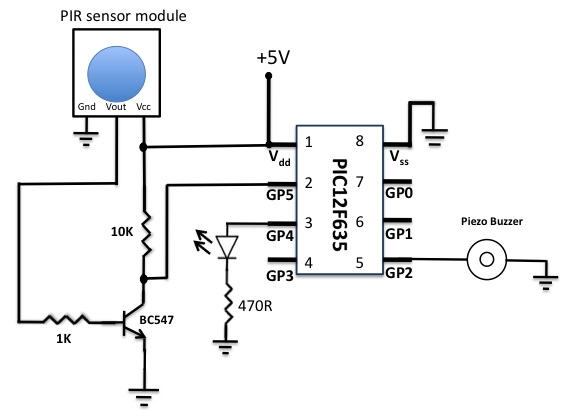
Pyroelectric sensor module,developed for human body detection. A PIR detector combined with a fresnel lens are mounted on a compact size PCB together with an analog IC (SB0061) and limited components to form the module. High level output (3.3V) of pre-settable variable width (5Secs -18 Minutes) is provided.
- What supply voltage is used for the circuit?
The circuit is powered by four AA batteries giving 6 V, with a series diode dropping it to about 5.4 V for the PIC. - Why is a diode used in series with the battery supply?
The diode drops the voltage to about 5.4 V to keep PIC operating below 5.5 V and provides reverse polarity protection. - Can rechargeable NiMH batteries be used?
Yes, the author tested NiMH rechargeable batteries (4.8 V) and it worked, though alkaline cells are recommended for better performance. - How is a 9 V battery accommodated?
If using a 9 V battery you need an LM7805 regulator IC in the circuit. - What voltage does the PIR sensor module output when motion is detected?
The PIR sensor module provides a high output of about 3.3 V when motion is sensed. - How is the PIR output interfaced to the PIC?
The 3.3 V PIR output drives the base of a BC547 transistor; the PIC monitors the transistor collector for full logic swing. - What is the collector voltage behavior with and without motion?
During normal condition the transistor is off and the collector is at logic high (+5 V); when motion is sensed the transistor saturates and the collector drops to logic low. - Which PIC pin monitors the PIR output?
The PIR-derived signal is monitored through GP5 (pin 2) of the PIC12F635. - What PIC oscillator and configuration are used?
The PIC12F635 uses its internal 4.0 MHz oscillator; MCLR is disabled and the watchdog timer is off. - What adjustable output timing does the PIR module provide?
The PIR module provides a pre-settable high-level output pulse width adjustable from about 5 seconds to 18 minutes.
