


Summary of Humidity and temperature measurements with Sensirion’s SHT1x/SHT7x sensors using PIC18F2550 (Part 2)
This article details Part 2 of a tutorial on interfacing Sensirion SHT11 and SHT75 humidity/temperature sensors with a PIC18F2550 microcontroller to display data on an LCD. It covers the circuit connections, communication protocols, software implementation in mikroC Pro for PIC, and specific code routines for resetting the interface and starting transmission sequences.Parts used in the Humidity and Temperature Measurement Project:
- Sensirion SHT11 sensor
- Sensirion SHT75 sensor
- PIC18F2550 microcontroller
- StartUSB for PIC development board
- 16×2 character LCD
- Decoupling capacitor (100 nF)
- External 8.0 MHz crystal
- Pull-up resistor (10 K recommended)
In Part 1 of this tutorial, we discussed about Sensirion’s SHT1x and SHT7x series of humidity sensors, their interface specifications, the communication protocol used for transferring data in and out of the sensor, and the equations to convert their digital outputs to actual physical quantities. These sensors are capable of measuring temperature along with relative humidity and provide outputs in fully-calibrated digital words. We will now see how a PIC microcontroller can be programmed to communicate with these sensors, read the temperature and relative humidity data, and display the information on a character LCD.
Circuit Diagram
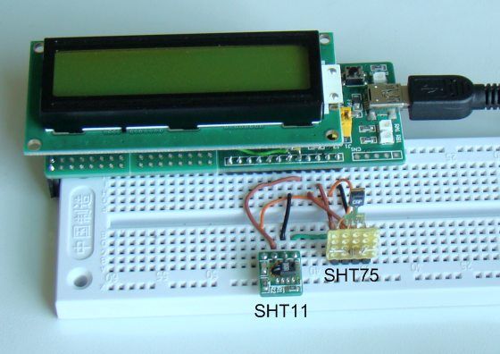
We will be interfacing the SHT11 and SHT75 sensors simultaneously to different port pins of PIC18F2550 and display the measured values of relative humidity and temperature from both on a 16×2 character LCD. The two sensors are placed next to each other and are supposed to measure the same values for relative humidity and temperature. The circuit diagram below shows the connection of the two sensors and a 16×2 character LCD to StartUSB for PIC board. StartUSB for PIC is a small development board for PIC18F2550 from mikroElektronika. The microcontroller comes preprogrammed with a bootloader, and therefore, no external programmer is required.
The LCD is operating in 4-bit mode, where the data pins D4-D7 are driven by RB4-RB7 pins of PIC18F2550. The RS and E pins are connected to RC6 and RC7 respectively. The clock lines of SHT11 and SHT75 are driven separately by RB1 and RB3 pins of PIC18F2550, respectively. On the other hand, the RB0 and RB2 pins are connected to the data pins (SDA or DATA) of SHT11 and SHT75, respectively. A decoupling capacitor (100 nF) is connected between Vcc and Gnd pins of each sensor. The PIC18F2550 microcontroller on-board StartUSB for PIC board runs at 48 MHz using the internal PLL along with an external 8.0 MHz crystal. A pull-up resistor of 10 K is required for each DATA line (in fact, the SHT11 board from mikroElektronika has pull-up resistors of 1 K on both DATA and SCK lines, but the manufacturer’s datasheet recommends 10 K).
Software
The sensor’s serial communication protocol was described in Part 1. We will implement it for PIC18F2550 using mikroC Pro for PIC. MikroElektronika provides a sample code written in mikroC for reading temperature and relative humidity from a SHT11 sensor. This code was later modified by Uroš Pešović (from Serbia) in order to account for the new conversion coefficients released by Sensirion for its version 4 sensors. I am adapting the same code for dual sensor case with some modifications that are required for our specific case.
The following subroutine is to reset the interface, in case the communication to the sensor is lost. In our case this routine will be always called before sending a new measurement command to the sensor. In order to pull the DATA line high, all you need is to define the direction of PIC port pin driving the DATA line as input. The pull-up resistor will then pull the line high. However, the same port pin direction must be defined as output and set to logic ’0′ to pull the line low.
void SHT_Reset() {
 SCL = 0;                     // SCL low
 SDA_Direction = 1;           // Define SDA as input to pull the DATA line high
 for (i = 1; i <= 10; i++)    // repeat 18 times
 SCL = ~SCL;                  // invert SCL
 }
Once the connection is reset, you need to send a Start Transmission sequence. The subroutine for this would be something like this.
For more detail: Humidity and temperature measurements with Sensirion’s SHT1x/SHT7x sensors using PIC18F2550 (Part 2)
Quick Solutions to Questions related to Humidity and Temperature Measurement Project:
- How are the LCD data pins connected to the PIC?
The data pins D4-D7 are driven by RB4-RB7 pins of the PIC18F2550. - Can this project be done without an external programmer?
Yes, the StartUSB for PIC board comes preprogrammed with a bootloader so no external programmer is required. - What clock frequency does the microcontroller run at?
The PIC18F2550 runs at 48 MHz using the internal PLL along with an external 8.0 MHz crystal. - Which pins control the clock lines for the two sensors?
The clock line for SHT11 is driven by RB1 and the clock line for SHT75 is driven by RB3. - Does the manufacturer recommend a 1 K or 10 K pull-up resistor?
The manufacturer's datasheet recommends a 10 K pull-up resistor for each DATA line. - What software environment is used to implement the communication protocol?
The protocol is implemented using mikroC Pro for PIC. - Why is the SHT_Reset subroutine called before sending a measurement command?
This routine resets the interface in case communication to the sensor has been lost. - How is the LCD configured for operation?
The LCD is operating in 4-bit mode.
Related projects
Pinguino Project: A PIC Microcontroller Based Arduino
This is a complete tutorial to make a PIC Microcontroller based Arduino. This is a complete tutorial to make PIC microcontroller based...
Audio, Sound & Radio · PIC18F2550LM386 based stereo audio amplifier with digital volume control using PIC18F2550
Due to its simplicity (requires minimum external components) and high availability, LM386 is very popular among hobbyists for use in low-voltage audio...
Meters & Test Instruments · PIC18F2550Harmonic Distortion Meter using PIC18F2550
The 3rd harmonic distortion meter has been designed for measuring the quality of AC supply. The meter is built with a PIC18F2550...
Sensors & TemperatureSpectrum Analyzer using TMS320F28023DA with Proteus Simulation
Introduction This project demonstrates a real-time audio spectrum analyzer using the TMS320F28023DA Piccolo microcontroller, simulated in Proteus VSM. The system captures an...
Sensors & TemperatureDHT22 Low Cost Humidity Sensor using PIC18F25K20 with Proteus Simulation
IntroductionThis microcontroller project demonstrates how to interface a DHT22 (RHT03) digital temperature and humidity sensor with a PIC18F25K20 using Proteus simulation.The project...
Sensors & TemperatureCrafting a Microcontroller-Based Temperature Monitoring System
Abstract As technological advancements progress, processes become increasingly intricate, demanding a corresponding expansion in the parameters necessary for efficient analysis. Data acquisition,...

Ibrar Ayyub
I am an experienced technical writer holding a Master's degree in computer science from BZU Multan, Pakistan University. With a background spanning various industries, particularly in home automation and engineering, I have honed my skills in crafting clear and concise content. Proficient in leveraging infographics and diagrams, I strive to simplify complex concepts for readers. My strength lies in thorough...