


Table of Contents
Introduction
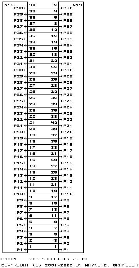
This is revision C of the EMDP1 mother board. It differs from revision B in that a 40-pin ZIF (zero insertion force) socket and an 80-pin `universal' plug have been added. This allows many chips to be programmed without requiring an adaptor board. When the `universal' plug is not enough, a specialized adaptor board may be employed.
Schematics
The parts list is kept in a separate file.
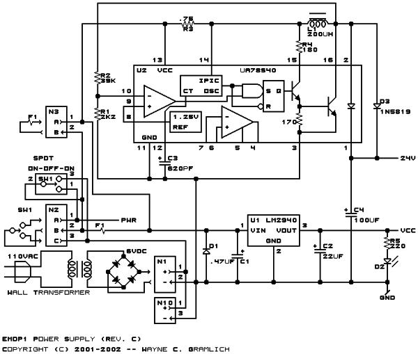
The power supply takes its power from either the SimpliciNet RJ45 connector N4 (shown as the wire labeled PWR) or from a wall wart connector, either N1 (on-board) or N10 (off-board). The on-off-on switch SW1 chooses between the two possible power sources. Diode D1 is a shorting diode that should short the supply and burn out the fuse F1 9on-board) or N3 (off baord fuse) if power somehow gets applied backwards. The C1, U1, C2 combination is a standard low voltage linear 5 volt supply using an LM2940 low drop out voltage regulator. The rest of the circuitry revolves around U2, µA78S40 switching supply chip which generates 24 volts from the input voltage of 6 volts. The design equations for the switching supply chip are in the appendix of the main EMDP1 design document.
The EMDP1 can communicate with its host processor via either RS-232 or RS-422 signaling. The RS-232 signaling takes place via an industrys standard female DB9 connector. The RS-422 signaling done via an RJ45 connector using standard Cat5 (catagory 5) cabling. The RS-422 is wired to conform to my SimpliciNet `standard', which allows both RS-422 signalling and power over the same cable.
 The RS-232 signals are converted to logic levels using U3, a standard MAX232 level convert chip. U4 is an RS-422 transceiver configured as an RS-422 transmitter and U5 is an RS-422 transceiver configured as a receiver. Resister R7 is 100 ohms of RS-422 termination and R8 and R9 provide biasing resistors to ensure that a logic high level is output if now RS-422 signal is present. U6A is takes the logical or of the received signals from the RS-232 and RS-422 and sends them on to the microcontroller serial receive line. U6B logically or's the transmit signals from the adaptor (via U11A) or from the microcontroller (MTX). R27 is forces the adaptor signal out if the microcontroller chip is being programmed by the bootstrap adaptor.
For more detail: EMDP1 -- Extensible Multiple Device Programmer 1 (Rev. C)
Related projects
Calculator Test using PIC24FJ64GA006 with Proteus Simulation
Introduction The Calculator Test using EASYHDL is a practical microcontroller project built on the PIC24FJ64GA006 and simulated in Proteus. This project demonstrates...
Programmers & ICSPPID Controlled Oven using TMS320F28027PT with Proteus Simulation
IntroductionThis project demonstrates a PID controlled oven implemented using a PICCOLO TMS320F28027PT microcontroller and verified through Proteus simulation.It is a practical microcontroller...
Programmers & ICSPPICCOLO Motor Controller Sample Design using TMS320F28023PT with Proteus Simulation
IntroductionThis project demonstrates a PICCOLO motor controller sample design implemented using the TMS320F28023PT Piccolo microcontroller and tested through Proteus simulation. It focuses...
Programmers & ICSP · PIC16F84APIC Musical Doorbell using PIC16F84A with Proteus Simulation
IntroductionThis microcontroller project demonstrates a musical doorbell built around a PIC16F84A and a simple piezo sounder.Using two push buttons, the system allows...
Programmers & ICSP · PIC16F877AEPE PIC/LCD Demo using PIC16F877 with Proteus Simulation
IntroductionThe EPE PIC/LCD Demo is a classic microcontroller project that demonstrates how a PIC16F877 can fully control a PG12864F graphical LCD.Designed as...
Programmers & ICSP · PIC16F628ADHT11 Low Cost Humidity Sensor using PIC16F628A with Proteus Simulation
IntroductionThis microcontroller project demonstrates how to interface a low-cost DHT11 temperature and humidity sensor with a PIC16F628A using a Proteus simulation environment.The...

Ibrar Ayyub
I am an experienced technical writer holding a Master's degree in computer science from BZU Multan, Pakistan University. With a background spanning various industries, particularly in home automation and engineering, I have honed my skills in crafting clear and concise content. Proficient in leveraging infographics and diagrams, I strive to simplify complex concepts for readers. My strength lies in thorough...