
Summary of DIGITAL SERVO MOTORS INTERFACE CIRCUIT PIC16F877
The project describes a PIC-based servo motor interface that converts RS232 serial commands from a PC into PWM servo control signals, supporting either 8 servos (PIC16F876) or 16 servos (PIC16F877). PCB designs and schematics were created with Eagle and Assembly PCB software.
Parts used in the Servo Motor Interface Circuit:
- PIC16F876 microcontroller (for 8-servo SER8 version)
- PIC16F877 microcontroller (for 16-servo SER16 version)
- RS232 serial interface components (RS232 level shifter such as MAX232 or equivalent)
- Crystal oscillator or clock source for PIC
- Capacitors for oscillator and decoupling
- Resistors as required for MCU and signal lines
- Servo connector headers (for 8 or 16 servos)
- Power supply components for servos and logic (voltage regulator, filtering)
- PCB fabricated via Assembly PCB software and schematics made with Eagle
PIC Microcontrollers Provide Multi-Servo Control
This project presents two servo motor control units based on Microchip PIC microcontrollers. The SER8 version uses a PIC16F876 to control up to eight servos, while the larger version uses a PIC16F877 for as many as 16 servo channels.
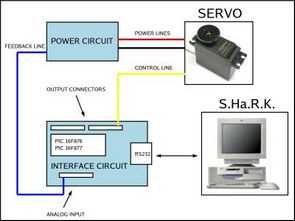
Both boards receive commands from a computer through an RS232 serial connection. This arrangement separates high-level commands from low-level servo timing, allowing software on the computer to request positions or speeds while the PIC generates the electrical control pulses required by the motors.
Servo Position Depends on Pulse Width
A standard hobby servo is normally controlled by repetitive digital pulses sent at roughly 20ms intervals. The position is determined primarily by the duration of the HIGH portion of each pulse rather than by changing the overall refresh period.
The project’s HIGH_TIME value represents this adjustable pulse duration. The supplied servo library hides much of this timing detail so application software can work with more intuitive angle or speed commands instead of manually calculating pulse widths.
Exact pulse ranges differ between servo models, so developers should check the specifications of the particular servo rather than assuming every device uses identical minimum and maximum timings.
Accurate Timing Helps Prevent Servo Jitter
Stable pulse timing is important because variation in the control signal can cause a servo to vibrate, make noise, or repeatedly correct its position.
The PIC firmware therefore needs to generate servo outputs consistently while also handling incoming serial commands. Timing routines should be designed so communication processing does not introduce excessive variation into the pulse signals.
This makes the project a useful example of real-time embedded programming, where several tasks must be coordinated without allowing one function to interfere with another.
SER8 and SER16 Provide Different Expansion Capacity
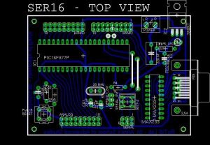
The SER8 board uses a 9×2-pin output connector providing eight servo control lines and a ground connection. The SER16 version expands this arrangement across two connector rows to support 16 servo channels.
The boards also provide analog inputs, an auxiliary serial connection, and I2C connectivity. The SER8 version offers five analog channels rather than eight because of the available resources on the PIC16F876.
These additional interfaces make the boards useful for more than simple servo positioning because sensors and feedback signals can also be incorporated into the control system.
Analog Inputs Can Monitor Servo Current
The analog channels can be connected to current-monitoring circuitry so the controller can measure how much current a servo is drawing. Each feedback signal connects to an analog-to-digital converter input on the PIC, allowing software to sample the measurement.
Current monitoring can provide useful information about mechanical load or abnormal operation. For example, an unexpectedly high current may indicate that a servo is stalled, overloaded, or attempting to move against an obstruction.
Current alone does not directly prove that a servo has reached its intended angle, however, so applications requiring precise position verification may need dedicated positional feedback.
Stable Power Is Critical for Servo Systems
Servos can draw large bursts of current when starting, changing direction, or operating under heavy load. The article notes that a medium-sized servo may briefly require around 2A, illustrating why the power supply should not be designed according to average current alone.
The supply should instead accommodate the combined peak or stall-current requirements of the connected motors. Starting every servo simultaneously can create a substantial current surge and cause voltage drops if the power system is undersized.
A separate or well-isolated logic supply can also help prevent servo current spikes from resetting the PIC or disrupting serial communication.
Servo Wiring Needs Low-Resistance Power Paths
High-current servo supply wiring should use wider PCB traces or conductors than low-current signal connections. Excessive resistance in the supply path can create voltage drops when several motors draw current simultaneously.
Bulk capacitance close to the servo connectors can help support short current transients, while local decoupling capacitors around the PIC and voltage regulator help reduce digital noise.
The servo supply and controller must still share an appropriate common ground so the control pulses have a valid electrical reference.
LM7805 Regulates the Control Electronics
The control board uses an LM7805 linear regulator to generate a regulated 5V supply from a higher input voltage. Appropriate input and output capacitors should be placed close to the regulator to maintain stability and suppress noise.
When using a linear regulator, designers should also consider power dissipation. The greater the difference between input and output voltage—and the larger the current—the more energy the regulator must dissipate as heat. An input near the upper end of the stated 7–16V range can therefore require additional thermal consideration.
Dedicated Servo Supply Handles Higher Current
Medium and larger servos should generally receive power from a supply designed specifically for their current requirements rather than drawing motor current through the microcontroller’s regulated logic supply.
The article suggests regulator options capable of producing approximately 5.5–6V for compatible servos. The correct voltage must always be chosen according to the servo manufacturer’s specifications because applying excessive or reversed voltage can damage the motor electronics.
Testing one servo at a time initially can help verify supply stability before additional channels are enabled.
MAX471 Provides Servo Current Feedback
The project uses a MAX471 current-sense device to monitor servo load current. Its output produces a signal proportional to the measured current, allowing the PIC’s ADC to convert the measurement into a digital value.
Because servo current changes rapidly as the motor moves and corrects its position, an RC low-pass filter can smooth the signal and provide a value closer to average consumption.
The MAX471’s current limit must also be considered when selecting the servo being monitored. A servo capable of exceeding the sensor’s supported current range requires a different sensing arrangement.
RS232 Connects the Controller to a Computer
Communication between the control board and PC uses an RS232 serial interface configured by default for 8 data bits, no parity, one stop bit, and 19,200 baud.
The project also includes switches that allow the MAX233 level-conversion circuit to be bypassed when direct logic-level serial communication is required. Care is necessary here because conventional RS232 voltage levels should not be connected directly to PIC UART pins.
The computer and controller must use matching baud rate and serial parameters or commands may be corrupted or ignored.
Startup Settings Can Be Loaded From EEPROM
A dedicated default switch determines how the servo controller obtains its startup values. In one position, predefined settings stored in the program are used; in the other, values previously saved to the PIC’s EEPROM can be loaded.
EEPROM storage is useful because it retains data after power is removed. This allows calibration or startup configuration to persist between operating sessions without requiring the user to enter the settings again.
Servo Outputs Start Disabled for Safer Operation
The project initializes servo outputs in a disabled state after power-up or reset. This is a useful design choice because uncontrolled movement during startup could cause mechanical collisions or create unexpectedly large current surges.
The controller can then enable channels only after valid settings and commands have been established. For robotic or multi-axis systems, controlled startup behavior is an important part of reliable servo management.
Practical Platform for Robotics and Motion Control
Combining multi-channel pulse generation, serial communication, EEPROM settings, analog feedback, and current monitoring makes this project more than a basic servo demonstration.
The same concepts can be applied to robotics, pan-and-tilt mechanisms, model systems, automated positioning equipment, and other motion-control projects. It also demonstrates why successful servo control requires attention to both software timing and electrical power design.
Source: DIGITAL SERVO MOTORS INTERFACE CIRCUIT PIC16F877
- What does this servo interface circuit do?
It translates servo commands received via RS232 serial connection into servo control signals using a PIC microcontroller. - Which microcontroller is used for the 8-servo version?
The 8-servo version (SER8) uses a PIC16F876 microcontroller. - Which microcontroller is used for the 16-servo version?
The 16-servo version (SER16) uses a PIC16F877 microcontroller. - How does the circuit communicate with the computer?
Communication with the computer is done via the RS232 serial port. - How many servos can the interface support simultaneously?
The interface can support either 8 servos (SER8) or 16 servos (SER16) simultaneously. - What software was used to create the PCB and schematics?
PCB files were made with Assembly PCB software and schematics were created with Eagle. - Does the circuit require additional components for RS232 signaling?
Yes, RS232 level shifting components (for example MAX232 or equivalent) are required for serial communication. - Are separate power supplies needed for servos and logic?
The project includes power supply components for servos and logic, implying appropriate voltage regulation and filtering are used.
