


Summary of Automated Railway Gate Controlled by PIC16F877A
Summary: This project automates a railway level crossing using a PIC16F877A microcontroller, two rail-placed pressure sensors, an LCD status display, traffic lights, and a motor-driven gate. When a train triggers the first sensor, the motor lowers the gate and swaps road/rail signals; after the train passes and triggers the second sensor, the motor raises the gate and restores road traffic. The design was simulated in Proteus and programmed in MikroC Pro.Parts used in the Automated Railway Gate Controlled by PIC16F877A:
- PIC16F877A microcontroller
- LCD display
- Pressure sensor (rail) - two units
- Traffic light (rail and road signals)
- Motor (for gate movement)
- Gate mechanism attached to motor
- Proteus simulation software (for testing)
- MikroC Pro compiler (for embedded C code)
Here I give you my project on Automated Railway Gate Controlled by PIC16F877A . It is very good project and if it is implemented by railway then they can save lots of money to paying salary for this purpose. For that project I use PIC16F877A, LCD display, two pressure Sensor (situated in rail line) ,Traffic light and motor (For closing and opening the railway gate).
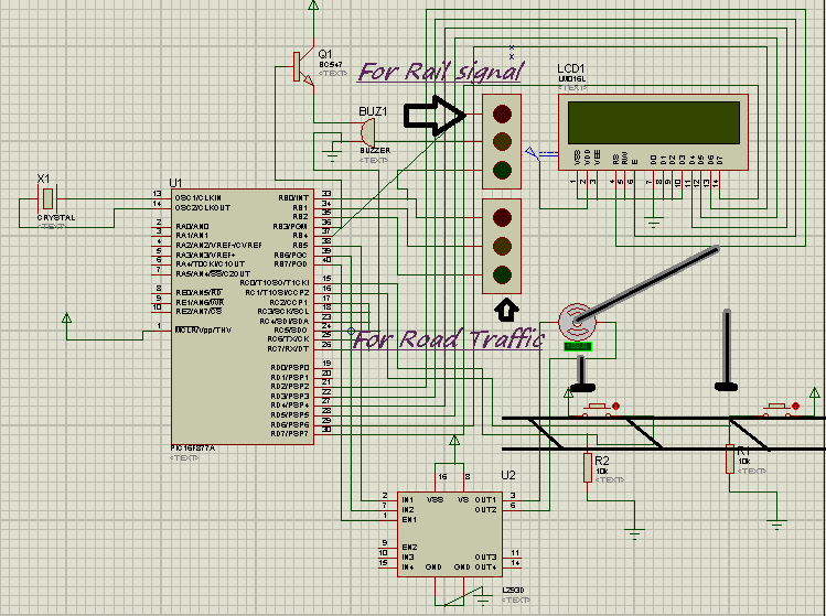
Project Detail: Here I use two pressure sensor places in rail line 1 km way from both side of rail gate. When Rail is coming and touch the first pressure sensor the motor is start rotating and the gate is attach with motor and it slowly down and close the door. Before close the door rail traffic light was red and for road traffic it was green. After closed the gate rail signal is green and road traffic is red. Now train cross the gate after crossing gate it will touch other pressure sensor which is situated 1 Km way from other side of crossing. Now motor start anticlockwise rotating and gate slowly opening and after complete opening of the gate road traffic light will green and railway signal will red. I used LCD to display the total status of railway gate control.
I use Proteus to simulate my project and Micro c pro for writing the embedded C . In bellow found the embedded code which I used.
For more detail: Automated Railway Gate Controlled by PIC16F877A
- What microcontroller is used in the project?
The project uses a PIC16F877A microcontroller. - How many pressure sensors are used and where are they placed?
Two pressure sensors are used, placed in the rail line 1 km from both sides of the gate. - What happens when the first pressure sensor is triggered?
When the first sensor is touched by the incoming train, the motor starts rotating to lower the gate and traffic signals are changed accordingly. - How does the system restore road traffic after the train passes?
After the train triggers the second sensor located 1 km beyond the crossing, the motor rotates anticlockwise to open the gate and road traffic light turns green. - What display is used to show gate status?
An LCD display is used to show the total status of the railway gate control. - Which software tools were used for simulation and coding?
The project was simulated in Proteus and coded using MikroC Pro. - What components control the traffic lights during gate operation?
The system controls traffic lights, setting rail traffic light green and road traffic light red when the gate is closed, and reversing when opened. - How is the gate physically moved?
The gate is attached to a motor which rotates to lower and raise the gate slowly.
Related projects
PIC16F877 Driving LCD in 4-Bit Mode using PIC16F877 with Proteus Simulation
Introduction This microcontroller project shows how a PIC16F877 can drive an LCD display using 4-bit mode inside a Proteus simulation.The project demonstrates...
Programmers & ICSP · PIC16F877AEPE PIC/LCD Demo using PIC16F877 with Proteus Simulation
IntroductionThe EPE PIC/LCD Demo is a classic microcontroller project that demonstrates how a PIC16F877 can fully control a PG12864F graphical LCD.Designed as...
Motors & Robotics · PIC16F877AEfficient Sun-Following Robot: A Solar Tracker with Microcontroller Control
Abstract The impending global challenge of dwindling non-renewable fuel resources underscores the urgency of transitioning towards renewable energy alternatives like solar power....
Home Automation & SecurityVoice Activated Power Sockets (Home Automation)
Yet another voice controlled home automation system! As shown in the picture, the system can control any electrical appliance, by turning ON...
Home Automation & SecurityHome Security System with GSM Using 8051 Microcontroller
Security is a big challenge everywhere because thefts are increasing day by day owing to the unsafe and insecure security systems in...
Home Automation & SecurityHome Automation and Security System using Microcontroller ATMEGA8 with Arduino Programming
Home automation and security systems have become very popular these days, today industrial automation techniques are widely adopted by luxurious homes and...

Ibrar Ayyub
I am an experienced technical writer holding a Master's degree in computer science from BZU Multan, Pakistan University. With a background spanning various industries, particularly in home automation and engineering, I have honed my skills in crafting clear and concise content. Proficient in leveraging infographics and diagrams, I strive to simplify complex concepts for readers. My strength lies in thorough...