


LED message system on a Strida folding bicycle wheel
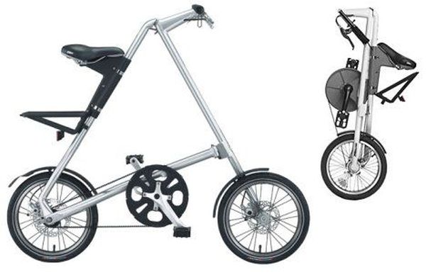
After I've bought my strida folding bicycle, one of the first things I've done was to check out instructables.com for any strida related projects. And quite astonished to see that there wasn't any.
So I've planned to make an instructable that can be used on my (and also others') strida.
I think this is the first (and only so far) project in instructables, which is built around the strida.
Though my expertise is electronical engineering and solar lighting systems, I've chosen to build a propel light for the strida. The improvement to the other propel lights around the web is to use solar power and to create a totally independent light system that "lives" inside the strida wheel. There is no wires to the outside world and no need to charge either.
The image generated is much better than the shaky photo below 😉
Electronical preparations
For the electronics, you may either go for scratch building or using some parts of a cheap solar garden light. I've done both ways. I've used this solar light that was wandering around my terrace for 2 years, one of which it was out of order.
I've disassembled it and found out it has perfectly good parts for this project.
first of them was a round solar panel. There is no fork in the unique strida bike design neither at the front nor rear. The folding ability is dependent on the magnet which connects the front-rear wheel axises. I've widened the small hole in the middle of the round solar panel wide enough the magnet mechanism of the strida wheel. By putting the solar panel in the middle, I also eliminated the balance problems of the wheel.
There are all kinds of small solar panels in these solar lights available everywhere. I guess finding a round solar panel which has got enough empty space in the middle which is enough wide to house the strida wheel axis is hard. But any other panel is ok too. all you have to do is obtain a power source which is able to deliver around 2.3v open circuit voltage and 50-200mA short circuit current. Mine is delivering 2.3v and around 200mA. its really perfect, a very lucky find.
Circuitry
I've designed a simple solar lighting circuit. It has got a small microcontroller a very simple charge controller and a voltage multiplier. The part at the lower left of the schematic is the voltage multiplier. It transforms the voltage generated by the 1.2V nimh cell to almost 4V which is enough for the ultrabright LEDs to run properly. The PIC12F675 microcontroller can work with voltages 2-6V so it is not problematic.
some of the solar garden lights have an internal voltage doubler too. Mine has got one too. But I've sticked to the circuit schematic. If you find one in your solar light, then you can use it instead of the one in the schematic. All you have to do is open circuit the LDR (light sensor, if there is any). I've did that to the doubler I've took from the disassembled light and put it a side for further use.

Next thing is to assemble the circuitry on multi holed prototype board. This will require some soldering and electronics assembly skills. I'm sure there are many instructables around this subject. You may take a look at them so I'm not mentioning about the assembly here. The photos are of the first light I've tried. It had 10 ordinary LEDs. I've designed a resistor network method for driving 10 leds with a controller having only 5 output pins. The method increased power consumption so I've gave up that. Later I'll make a second version with a bigger controller and 10 or more LEDs. This version of the circuit has got 5 LEDs.
The circuit is secured to the air valve of the tire. I've used a metal valve cap and used hot silicone to glue circuit to the cap.
The proteus simulation file (demo is available on labcenter.co.uk ) is also included for the ones who want to see the circuit working.
 strida5.DSN73 KB
Related projects
PIC 12F675 Programmable 12V Battery Monitor
Being an active outdoor guy, I have a few different types of 12V lights and a variety of battery types. - For...
Audio, Sound & Radio · PIC12F675Audio CRO using PIC12F675 Microcontroller
This project is a miniature Audio CRO. For those not familiar with the abbreviation "CRO," it means "Cathode Ray Oscilloscope" and this...
Development Boards & Kits · PIC12F675DIY $1 PIC 12f675 JDM Programmer (Cheap and Easy)
Hi EveryBody i am Again Doing something. and it is with PIC's! Almost Everybody do not want a Big Arduino in their...
Games, Toys & CalculatorsExploring Leon’s Mini Random Number Generator (mRNG)
Sales Pitch Feeling overwhelmed by choices? Who isn't? Decision-making can be a maze. White, rye, or wheat? Pinstripes or polka dots? Feast...
Games, Toys & Calculators · PIC16F628ATIC TAC TOE game using PIC16F628
This project is not to introduce Tic Tac Toe. Everyone knows this game. It's to introduce two features. Bi-coloured LEDs, microcontrollers and...
Games, Toys & CalculatorsInteractive Blitz Chess: A Physical Blitz Chess Board Powered with PIC32
Introduction We created a companion system for physical chess boards to help players enjoy their fast paced blitz game with a chess...

Ibrar Ayyub
I am an experienced technical writer holding a Master's degree in computer science from BZU Multan, Pakistan University. With a background spanning various industries, particularly in home automation and engineering, I have honed my skills in crafting clear and concise content. Proficient in leveraging infographics and diagrams, I strive to simplify complex concepts for readers. My strength lies in thorough...